
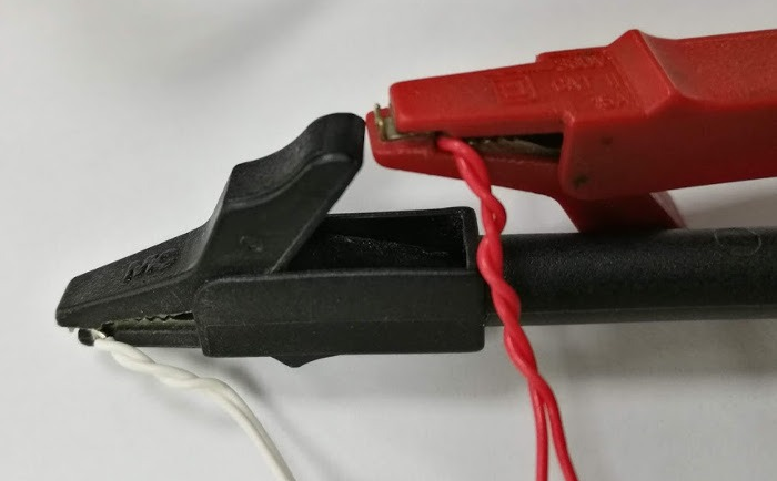
 How to check the faulty temperature sensor?
Sometimes the sensor will be damaged or degraded in a harsh environment. You may experience intermittent thermocouple failure or the instrument may display "open circuit". The following is a guide for checking thermocouple and resistance thermometer problems to diagnose various failure modes to help you correct this condition.
Troubleshooting steps for fault temperature sensor:
● Check if - ve and+ve leads are correct
● Check whether the type of cable you use is correct
● Check for local heat sources that affect readings
● Check the temperature controller/reading settings
● Resolve out of scope errors
● Resolve sensor open circuit/open circuit error
● Physically check whether the sensor is damaged
● Check the temperature transmitter
● Use a multimeter to test the faulty thermocouple
● Test the faulty resistance thermometer with a multimeter
● Contact experts 18717811268/ sales@weilianchina.com
How to test a faulty thermocouple or resistance thermometer?
The first indication that the thermocouple or pt100 sensor is not working properly will come from the instrument to which it is connected. The reading may be lower or higher than expected, or the instrument will display an error code.
Instruments connected to thermocouples or pt100 are usually temperature controllers or readers.
Depending on the brand and model, different errors on the controller will mean different things. Check your temperature controller manual to ensure that it is not the fault of the controller itself.
Check if the - ve and+ve leads are interchanged
If your temperature sensor is a resistance thermometer, swapping the - ve and+ve leads will not affect the reading.
If the wires are not connected correctly, the thermocouple readings will change.
If - ve and+ve leads are exchanged between the thermocouple and the instrument, the reading will change relative to the ambient temperature, for example, a reading of 100 ° C and an ambient temperature of 25 ° C will read 75 ° C if the leads are not connected correctly. Make sure that the - ve thermocouple leads and the+ve thermocouple leads are properly connected to your instrument.
Check any thermocouple cable wiring problems
Compensation cable wiring error
Incorrect wiring of thermocouple cables can be more complex, as thermocouples often use compensating cables. The compensating cable may be incorrectly connected to the thermocouple. The wiring on the instrument may be correct, but the wiring between the thermocouple and the compensating cable is incorrect. To avoid this, make sure that the - ve and+ve legs are correctly matched along the entire length of the thermocouple, with the compensating cable, and with the instrument.
Use wrong compensation type
Each compensating cable is also connected to a specific thermocouple type. To ensure accuracy, you must only use the same type of compensation cable, for example, K-type thermocouple can only use K-type compensation cable for expansion. Sometimes other types of cables, such as general-purpose instrument cables or copper cables, are used to extend thermocouples, which can also lead to errors.
Use compensation cable in high temperature environment
The last quirk of the compensating cable is that it should not be used in high temperatures. The rated temperature of thermocouple compensation cable is lower than that of thermocouple cable. Try using compensating cables at ambient temperatures to reduce errors.
Check the local heat source problem
If your thermocouple reading is too high, it may be because your sensor is too close to the heat source. If your sensor is close to a local heat source, it may increase the measured temperature, not where you want to measure the temperature.
Check the temperature transmitter settings
If your sensor uses a temperature transmitter, it is important to check whether the output of the transmitter is the same as the input of the instrument. The most common signal range is 4... 20 mA.
Check the temperature controller settings
Check the input settings on the temperature controller
For example, if your temperature controller is set to an S-type input, but a B-type thermocouple sensor is connected, it will display an incorrect temperature and cause you to think that your sensor is malfunctioning. You need to ensure that the input selected on the controller matches the type of thermocouple or resistance thermometer to which it is connected.
There are also controller errors that indicate a problem with the temperature sensor.
Instrument display: input signal is above or below the limit value (out of range error)
The controller may display something indicating that it believes there is an out of range error. Common controller brands may display:
| brand | Signal below limit | Signal overrun |
| 1 | uuuu | nnnn |
| 2 | LLEr | HLEr |
| 3 | LLLL | HHHH |
| 4 | uuuu | oooo |
Each brand and model of controller is different, so check your temperature controller manual to see how out of range errors will be displayed on your specific model.
If an out of range error occurs, the input provided by the temperature sensor is outside the expected range based on the input configured on the controller.
For example, if your controller is set to an S-type thermocouple input, expect a small range of mV. If you subsequently connect an E-type thermocouple, a thermocouple with a higher mV range will display an out of range error at 300 ° C.
Instrument display: sensor open circuit error (open circuit)
If the controller displays an open circuit error, the connection to the sensor is incomplete. This may mean that one of the sensor terminals is not connected to the controller, or there is an interruption somewhere in the sensor.
Common controller brands may display:
| brand | Sensor disconnection error |
|---|---|
| 1 | oPen |
| 2 | SbEr |
| 3 | Sbr |
| 4 | ---- |
Each brand and model of controller is different, so please check your temperature controller manual to see how the sensor damage error will be displayed on your specific model.
If you have checked whether the sensor is correctly connected to the controller, but there is still an open circuit error, you need to disconnect the sensor and take it out of the process to further test whether the thermocouple or resistance thermometer is faulty.
Perform a visual inspection of the temperature sensor
After removing the sensor from your process, visually inspect the damage along the length of the jacket and the measuring points. On the thermocouple, the tip has a measuring junction, and on the resistance thermometer, the tip has a element, such as pt100 element.
If there is any breakage on the sheath or the tip of the sensor is damaged, it may be the cause of the fault. If there are no visual problems, you can use a multimeter to verify any internal interrupts.
Use a multimeter to troubleshoot the temperature sensor
Inspection of thermocouple multimeter in the head
One check that you can make with thermocouples is whether the+ve and - ve wires in the terminal connector are shorted. If the instrument and any compensating cables are set correctly, the instrument will provide environmental readings.
Test the faulty thermocouple with a multimeter
Obtain the faulty thermocouple and multimeter.
Change the multimeter to continuous buzzer/diode symbol/current flow. Some multimeters will emit a beep when they are disconnected, and some multimeters will emit a beep when they are disconnected. Understand the function of the multimeter.
Diode symbol:
Two multimeters display the selected diode/continuity buzzer settings: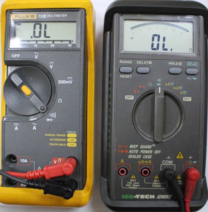
Connect each leg of the thermocouple to the multimeter. The directions of the front and back legs do not matter.
After connecting the thermocouple to the multimeter, the working thermocouple will emit a beep (if the multimeter works in the opposite way, it will not emit a beep). The screen will display a resistance in ohms, which may be zero. If there is an interruption, it will display OL or something similar.
If you encounter an intermittent thermocouple failure, you can adjust the position of the sensor and its leads to see if the failure can be triggered.
Use a multimeter to test the faulty resistance thermometer
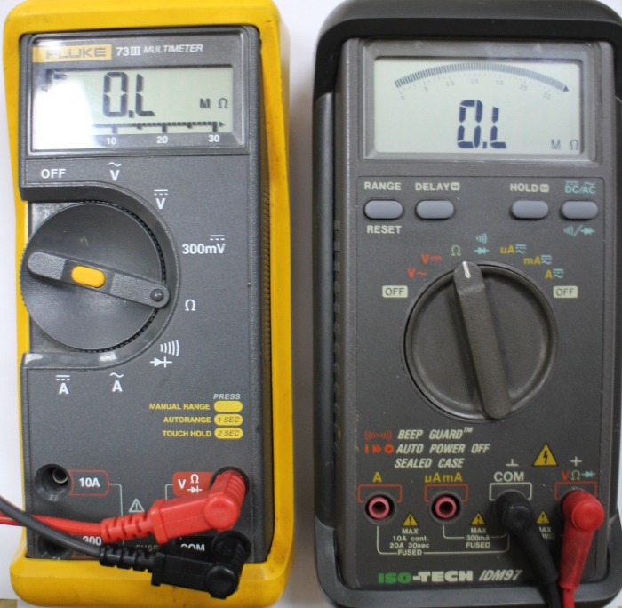
After removing the faulty resistance thermometer, obtain a multimeter and change it to the ohm setting (Ω).
Two multimeters showing the selected ohm (Ω) setting:
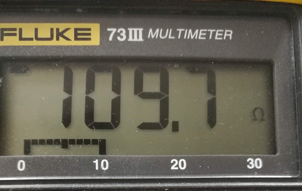
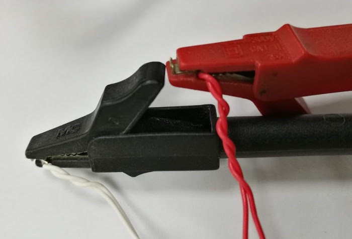 If your resistance thermometer is connected to a multimeter and the reading is 0 ohms, the sensor may be damaged. You can move any flexible cable or tail around in an attempt to trigger any intermittent fault. In the working resistance thermometer, the multimeter will read the ohm value. The example table is as follows:
| Ohm reading at room temperature (20-25°C) | Resistance thermometer type |
|---|---|
| 107.793-109.735Ω | pt100 |
| 538.967-548.673 Ω | pt500 |
| 1077.935-1097.347Ω | pt1000 |
| ~0Ω | The sensor is damaged or not a resistance thermometer |
The tolerance of these values depends on the accuracy of the resistance thermometer and the actual temperature of the room.
The sample resistance thermometer reads 109.7 ohms, approximately 25 ° C:
Contact peak sensor
The above guidelines are intended to help you identify problems with resistance thermometers and thermocouples. Peak Sensors is an expert in temperature sensors. The shortcut to solve your temperature problem is to contact us. We can help solve your sensor problems and repair or manufacture replacement sensors.
Call us: 18717811268
Email us: sales@weilianchina.com

