 Formulas for 2-wire RTD temperature sensors, 3-wire RTDs, and 4-wire RTDs
2-wire RTD temperature sensor:
where
● Rpt is the resistance of RTD
● R2 is the resistance of the first conductor (extension wire used to connect RTD)
● R3 is the resistance of the second conductor (used to connect the extension wire of RTD)
● L2&L3 are extension lead wires
The wire resistances R2 and R3 are inevitably included in the measurements. Wire resistance can be eliminated by calibration, but only at a specific temperature (usually room temperature) of the wire.
Also read: 2 线 RTD、3 线 RTD 和 4 线 RTD 之间的区别Difference between 2-wire RTD, 3-wire RTD and 4-wire RTD
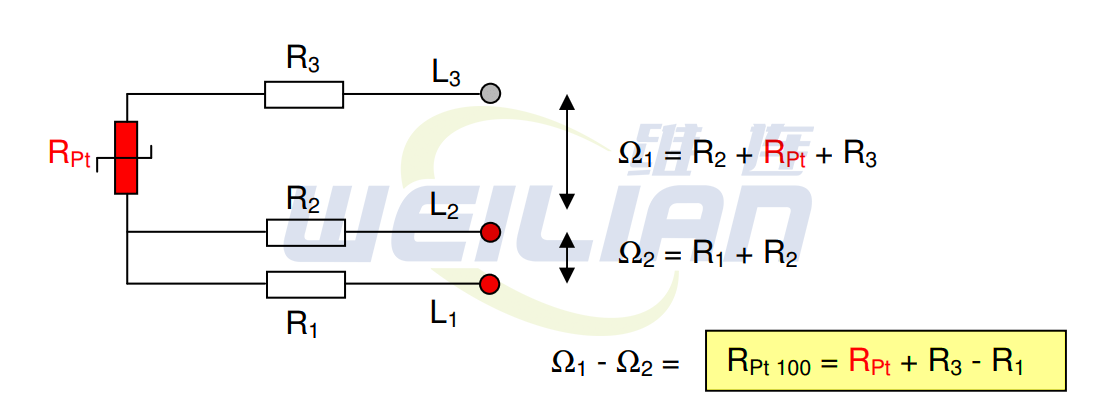
3-wire RTD:
where
● Rpt is the resistance of RTD
● R1 is the resistance of the first conductor (used to connect the extension wire of RTD)
● R2 is the resistance of the second conductor (extension wire used to connect RTD)
● R3 is the resistance of the third conductor (used to connect the extension wire of RTD)
● L1, L2 and L3 are extension cable leads
● Ω 1 is the total resistance between leads L2&L3
● Ω 2 is the total resistance between leads L1 and L2
You only measure the true Pt100 resistance when and only when the wire resistances R1 and R3 are equal. Since wire L2 is also red (and difficult to trace), you must keep all wire resistances R1, R2, and R3 equal.
Also read: Differences among RTDs, thermocouples and thermistors
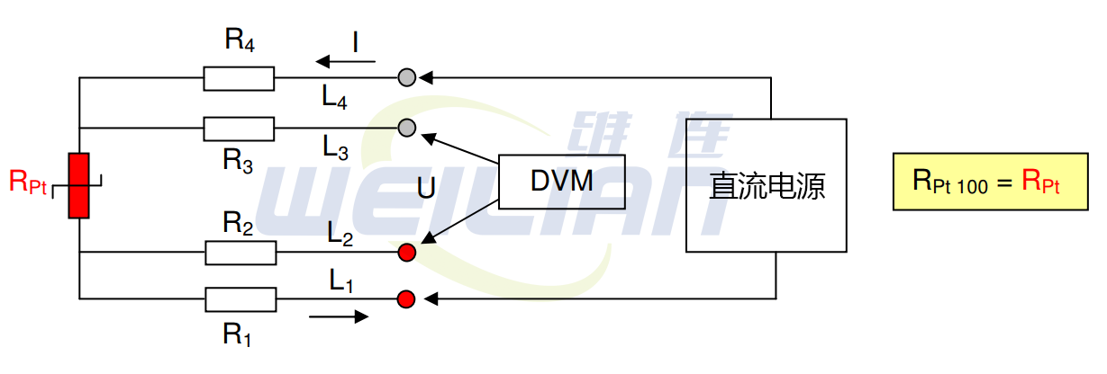
4-wire RTD:
The current source will keep the excitation current constant (0.1 – 1 mA). Following Ohm's law, R=U/I, the resistance can be calculated. The input impedance of digital voltmeter DVM shall be at least 10 megohms.
Therefore, only a very small current will pass through the DVM, which means that the voltage drop across the wire resistances R2 and R3 is almost zero.

