How does a 4-wire RTD temperature sensor work?
Principle of 4-wire RTD temperature sensor
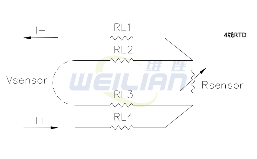
The most accurate leader configuration is the "real" 4-wire configuration. In a true 4-wire configuration, the resistance of the lead does not affect the resistance of the sensor.
The 4-wire structure is mainly used in places where precision is required. In a 4-wire RTD temperature sensor, the actual resistance of the lead can be determined and removed from the sensor measurement.
The true 4-wire measurement uses the current potential method. A current of a known value (I+) passes through the sensor along the "current" lead. The voltage generated at both ends of the sensor is measured using the "potential" lead (Vsensor), and the resistance of the sensor is calculated by dividing the measured voltage by the known current.


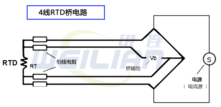
The 4-wire circuit is a real 4-wire bridge. Its working principle is to use wires 1 and 4 to supply power for the circuit, and use wires 2 and 3 to read. This true bridge method will compensate for any differences in lead resistance.
The resistance of the leads is not a factor because:
The current value is equal at any point in the circuit. It is independent of the resistance of the leads.
The input impedance of the voltage measuring circuit is high enough to prevent any significant current in the voltage leads. Since there is no current flow, the voltage along the potential lead does not change along its length.
4-wire RTD temperature sensor bridge circuit

