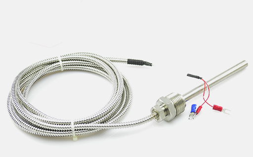
 Influence of Lead Resistance on RTD Temperature Sensor
RTDs typically use copper leads connected to platinum components. These leads are usually connected close to the element and close to each other (so that the two nodes are at the same temperature) to prevent Seebeck voltage from also affecting the measurement.
However, the resistance of the copper wire will still have a negative impact on the measurement, especially when the RTD temperature sensor element is far away from the measuring instrument, or when a two-wire RTD sensor is used. The increase in resistance of long copper leads will also reduce the signal to noise ratio of RTD temperature sensors, especially when using low resistance RTD elements. Using only three or four wire RTD sensors can minimize the negative impact of lead resistance and compensate for lead resistance errors when coupled to compatible instruments.
For example, please note that the resistance of the copper wire changes about 0.4%/° C around 25 ° C. Similarly, the change rate of platinum RTD element is 0.00385 Ω/Ω/° C, or 0.385%/° C is close to 25 °.
Note that the 30 AWG copper wire is approximately 0.105 Ω/ft. Therefore, a 100 foot long, two-wire, 100 Ω platinum RTD temperature sensor element with 30 AWG leads will have a 10.5 Ω/lead or 21 Ω sensor loop IR voltage drop. For a temperature span of 0-100 ° C, this indicates a 38.5 Ω change in element resistance.
Therefore, in a 2-wire configuration, the lead contributes 21 Ω/38.5 Ω or up to 55% error. In addition, as the temperature coefficient of copper resistance is slightly higher than that of platinum at 0.4%/° C and 0.385%/° C, the lead resistance will exceed the growth of platinum components with the increase of temperature, resulting in the actual increase of error as temperature rise.
Of course, a wider temperature span will reduce this error, but even if the span is 0-500 ° C (100-280.98 Ω), 21/180.98 or 12%, it is still important. Most importantly, two-wire RTD temperature sensors may only be useful when the RTD temperature sensor is close to the measuring instrument.
For 2-wire sensors without compensation, lead resistance is a major problem. Some instruments do roughly compensate for two-wire sensors by allowing you to enter the measured lead resistance as part of the instrument configuration.
However, this is only effective when the lead is kept at a constant temperature, because changes in ambient temperature change the resistance of the lead. When the sensor element has high resistance and the lead wire has low resistance, or when the sensor is close to the instrument, the two-wire sensor connection may be OK, but it should be carefully considered.
To calculate the possible error caused by an uncompensated two-wire sensor connection, multiply the length of the two extenders by their resistance per unit length. This resistance is then divided by the sensitivity of the element (its TCR) to approximate the error.
For example, a two-wire Pt RTD 100 feet from the instrument and wired with a 24AWG extension cord (26.17 Ω/1000 feet)( α= 0.0038500 Ω/Ω/° C) may cause the following approximate errors:
(2*100ft*26.17Ω/1000ft) / 0.385Ω/°C
= 5.234Ω/0.385Ω/°C
=13.59°C
This is equivalent to the resistance value of the lead and the sensitivity of the element divided by it (sensitivity=R0* α
= 100Ω*0.00385Ω/Ω/°C
= 0.385Ω/°C)。

