4 -line temperature transmitter current circuit
4 line ("self -power supply") temperature transmitter current circuit
The DC current signal can also be used to transmit the process measurement information from the temperature transmitter to the controller (PLC/DCS), indicator, recorder, alarm and other input devices. Recall that the purpose of the temperature transmitter is to detect some physical variables (such as pressure, temperature, flow), and then report the amount in the form of signals. In this case Positive proportional.
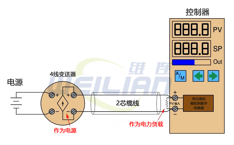
The simplest form of 4-20 MA measurement loop is that the temperature transmitter has two terminals to connect the 4-20 MA signal line, and the other two terminals are used to connect the power supply. These transmitters are called "4 -line" or "self -power supply" devices. The process variable input terminal from the current signal connection to the controller from the temperature transmitter to the controller to complete the loop:
Note:
● In this article, we assume that a simple microcontroller -based controller is connected to a 4 -wire transmitter.
● For the PLC/DCS system, the standard resistor and modulus converter (ADC) can be found in the analog input (AI) card.
Some processes controllers are not equipped with direct acceptance signals, but can only explain DC voltage signals. In this case, we must connect a precision resistance on the input terminal of the controller to convert the 4-20 mA temperature transmitter signal to the standardized simulation voltage signal that the controller can understand.
The voltage signal range of 1 to 5 volt is standard. Although the controller of certain models uses different voltage range, different precision resistance values are required. If the voltage range is 1-5 volts and the current range is 4-20 mA, according to the law of Ohm, the precision resistance must be 250 ohm.
Since this is a digital controller, the input voltage on the controller terminal is explained by the modulus converter (ADC) circuit, and the circuit converts the measured voltage into numbers that the controller microprocessor can explain.
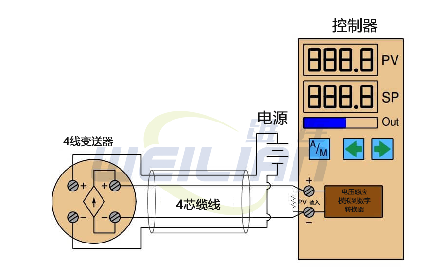
In some installations, the temperature transmitter power is provided from the power supply near the controller through the additional wires in the cable:

The obvious disadvantage of this scheme is two more conductors in the cable. More conductors means that for the given length, the diameter of the cable will be larger and more expensive. Cables with more conductors will require a larger wire catheter to insert, and all on -site wiring boards must include more wiring terminals to marshall be added with additional conductors. However, if the location of the temperature transmitter does not have a suitable power supply, you need to use the 4 -cable to maintain the 4 -line temperature transmitter.

