4-20 ma Temperature Transfer Wiring Type: 2 line, 3 lines, 4 lines
The transmitter can provide a variety of signal outputs. The 4-20MA analog signal is by far the most commonly used signal in industrial applications. There are several physical 4-20mA wiring options. This guidance describes these options.
Industrial transmitters can be used to monitor many parameters, including pressure, temperature and traffic. The gas detector/transmitter provides a 4-20mA output, of which 4 mA is equivalent to zero readings, and 20 mA is equivalent to the full volume reading of the calibration range. The signal was sent to the remote control panel. The control panel uses the signal and activate the execution action through the contact of the relay. For example, sound and visual alarm or start some cards or even factory closure procedures.
Temperature transmitter usually requires 24VDC power. This power can be obtained from the transmitter or directly from the relevant control panel.
4-20 ma transmitter wiring
There are multiple temperature transmitter wiring options. The design of the relevant control panel determines which option should be used.
These wiring options include:
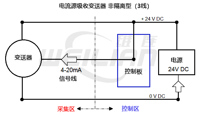
● Current source transmitter, non -isolation (line 3)
● Current absorption transmitter, non -isolation (line 3)
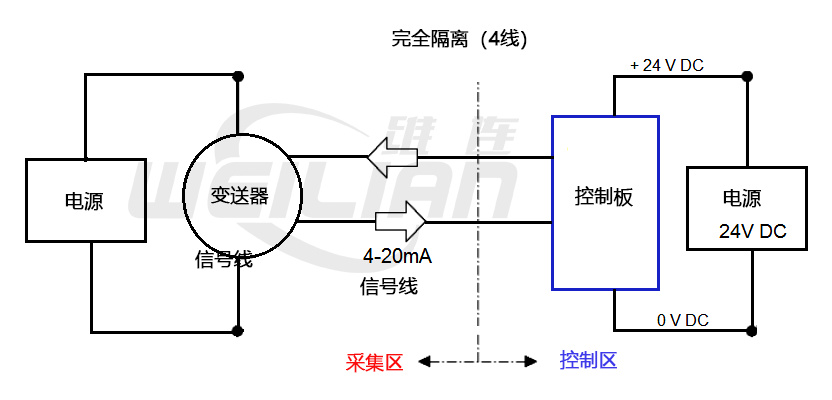
● Completely isolated (4 lines)
● Variables for power supply on the two -line circuit
Most modern transmitters can use current remittance or source format wiring, which are usually selected by using the position of a specific terminal or the inner link of the transmitter.
However, some transmitters may be limited to receivers or source configurations. Check the transmitter technology manual to understand the available options.
When the transmitter configures the terminal with a current source, the control system will be a current absorber, and vice versa.
Therefore, it is important to determine whether the transmitter or the control system that uses a specific configuration wiring.
For the purpose of this guide, assuming that the transmitter and the remote control panel require 24VDC power.
current source transmitter, non -isolation (3 line)
This is the most common configuration of the modern 4-20mA transmitter.
The transmitter and the control panel can use the same 24V and 0V DC power cords.
The 4-20mA signal flows through the 24V DC and the signal line to the controller.

Benefits
● The transmitter only needs three cable cores.
● Both transmitters and control panels can be used by public power.
Disadvantages
● Any electrical interference or pickup may be transmitted along the signal line, which may generate false alarms in the control panel
Current absorption transmitter, non -isolation (line 3)
The transmitter and control panel can use the same 0V and 24V DC power cords. The 4-20mA signal flows through the 0V DC line and signal line to the controller.

benefits
● The transmitter only needs three cable cores.
● Both transmitters and control panels can be used by public power.
Disadvantages
● Any electrical interference or pickup may be transmitted along the signal line, which may generate false alarms in the control panel.
Complete isolation (4 lines)
The transmitter and control panel use a separate power supply. 4-20mA signal flows through the two independent cable cores between the transmitter and the control panel.
Suppose the power supply drives the 4-20mA circuit comes from the control panel.

benefits
● The electrical interference on the power line will not be transferred to the 4-20mA signal line, thereby reducing the risk of the controller received the false signal.
Disadvantages
● Compared with the current absorber and the current source option, each transmitter needs additional cable core cable.
● The transmitter and the control panel require a separate power supply.
Two -line circuit power supply transmitter
This configuration provides power and 4-20MA signals through the two-line loop connection between the transmitter and the control panel.
Not all transmitters can use this format wiring, and must be designed to adapt to this configuration.

Benefits
● Has low power consumption.
● The transmitter only needs two cable cores.
Disadvantages
● The transmitter discrete fault signal cannot be set to 0mA, because this configuration continues to consume some current under the condition of fault. This configuration does not apply to the control panel that requires a 0MA signal for failure instructions.
Due to the reduction of the MA range available between faults and zero reading, the state signal below 4mA is limited. It is not suitable for power -consuming transmitters, such as catalytic gas detectors or infrared gas detectors using optical heating elements.

