Selecting and using temperature sensors
Thermocouple or resistance temperature detector (RTD) -- the measurement of the characteristics is an important part of most industrial operations, which is usually realized by a temperature sensor in contact with the solid surface or immersed in the fluid. Although these sensors have overlapping temperature ranges, each has application specific advantages.
| Selection Guide for Temperature Sensor | ||
| second | Thermal resistance | Thermocouple |
| temperature range | ??200°C to 850°C | ??190°C to 1821°C |
| second | ??328°F to 1562°F | ??310°F to 3308°F |
| accuracy | ±0.001°F to 0.1°F | ±1°F to 10°F |
| response time | secondary | apace |
| stable | Long term stability | Not very stable |
| second | <0.1% error/5 years. | 1 ° F error/year. |
| Linearity | best | secondary |
| sensitivity | high sensitivity | Low sensitivity |
When selecting a sensor type for a particular application, several factors must be considered: temperature range, accuracy, response time, stability, linearity, and sensitivity. Table 1 summarizes these. RTD is the preferred sensor when sensitivity and application flexibility are the most important criteria. However, RTDs are more expensive than thermocouples in terms of component costs. Therefore, selecting the perfect sensor for a particular application requires an understanding of the basics of RTDs and thermocouples.
Fundamentals of RTD Temperature Sensor
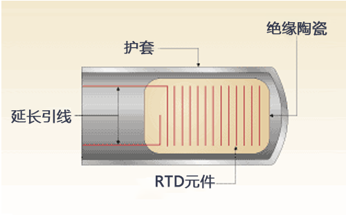
 图1。
图1。
RTDs are available in 2-wire, 3-wire, and 4-wire configurations, but their basic components are the same. These sensors measure resistance changes caused by temperature changes.
The working principle of RTD is that the resistivity increases with temperature. RTDs are usually made of platinum, nickel, or copper. The copper and nickel versions operate in a lower temperature range and are cheaper than platinum. Platinum is the most widely used material because of its wide temperature range (?? 200 ° C to 850 ° C), excellent repeatability, stability, and chemical and corrosion resistance. Platinum RTDs have nominal resistance values of 100 (omega), 200 (omega), 500 (omega) and 1000 (omega) at 0 ° C, of which 100 (omega) is the most popular.
The basic structure of RTD is very simple. The sensing element is connected to the lead wire and supported by an insulator (such as glass, mica or ceramic) and placed in a protective sleeve (see Figure 1). The detector is available in 2-wire, 3-wire, and 4-wire configurations.
The 2-wire version is ideal for applications where the sensor is connected directly to the receiver to prevent lead length resistance errors, which led to the development of more accurate 3-wire and 4-wire configurations.

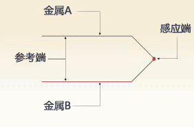
Figure 2
The thermocouple measures the temperature by detecting the voltage change at two different metal nodes. The voltage increases as the temperature increases.
When the distance between the sensor and the receiving instrument is very long, a 3-wire unit is used. Although their accuracy is lower than that of 4-wire detectors, they are sufficient to meet the needs of many industrial applications.
In a 4-wire configuration, one pair of leads provides the excitation current for the RTD and the other pair measures the voltage at both ends. This technology significantly minimizes the lead voltage drop and provides high accuracy.
Thermocouple basics
The thermocouple is composed of two different metals, which are connected together at one end and generate voltage (expressed in millivolts) as the temperature changes. The connection point of two metals is called the inductive connection point, which is connected to the extension wire (see Figure 2). Any two different metals can be used to make thermocouples. Among numerous candidate combinations, ISA identified 12. Most of these thermocouple types are named with a single letter; The most common are J, K, T, and E. The composition of thermocouple is international standard, but their wire color codes are different. For example, in the United States, the negative lead is always red, while the rest of the world uses red to represent the positive lead.
Thermocouples can easily introduce measurement errors. Since the voltage generated by the thermocouple is due to the combination of two different metals, introducing other junctions into the circuit will cause voltage changes, which is called cold junction error. If the temperature at the connection is determined, these errors can be corrected by a process called cold junction compensation. This is performed on a receiving device (usually a signal conditioner).
Thermocouples are also available in three junction types: grounded, ungrounded, and exposed.

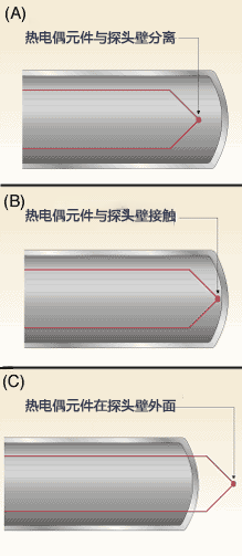
Figure 3
Thermocouples are divided into three junction types. The sensing junction of the grounding device is directly connected to the probe wall (A) to ensure good heat transfer from the outside to the junction. The connection point of ungrounded type (B) is separated from the probe wall, resulting in a slower response time than that provided by grounded equipment. When rapid response time is required, the sensing junction of the exposed thermocouple (C) is located outside the sheath and exposed to the environment.
The sensing junction of the grounded thermocouple is directly connected to the probe wall. This results in good heat transfer from the outside through the probe wall to the thermocouple junction (see Figure 3A).
The connection point of ungrounded thermocouple is separated from the probe wall. This type of response time is slower than the grounding type (see Figure 3B). When the response time is the decisive factor in selecting the thermocouple probe type, it is better to use the exposed thermocouple (see Figure 3C). In this type of probe, the sensing junction protrudes from the tip of the sheath and is exposed to the surrounding environment. Ungrounded thermocouples provide the best response time, but should not be used for corrosive or pressurized applications.
Temperature measurement decisions can determine the expected results of the process. Selecting the right sensor for an application may be a difficult task, but processing the measured signal is also critical.
Function of signal conditioner
Once the temperature sensor is selected, it must be integrated into the control system, which is usually based on DCS or PLC. One integration method is to connect RTD or thermocouple leads directly to the controller. This technology requires a special temperature conversion card. The multi-channel temperature card can be used for different controllers, but it is expensive and does not provide system flexibility.
Another method, temperature signal conditioner, has become very common in the industry due to the advantages it provides: precision, noise resistance/isolation, system flexibility/diagnosis and cost saving.
Accuracy. The development of the temperature signal conditioner is to maintain the integrity of the sensor output. Their precision specifications exceed those of PLC or DCS cards. Adjusting the sensor signal near the measuring point can prevent signal degradation due to errors caused by thermal gradient of thermocouple and imbalance of resistance of RTD lead.
Anti noise/isolation. The level of thermocouple and RTD signals is very low, so they are very vulnerable to noise. The signal conditioner can convert this low level signal to 4?? 20 mA output, which is less affected by noise and can run for longer distances. The regulator also provides low-pass filtering to prevent high-frequency noise from passing through the controller. The signal conditioner also provides isolation to prevent inaccuracies due to ground loop problems that are common in temperature measurements.
System flexibility/diagnostics. The signal conditioner provides complete flexibility for the control system. 4?? The 20 mA measurement signal can be directly sent to the recorder or analog card. Some complex temperature regulators provide analog and digital outputs for alarm or emergency shutdown. The module also provides local and remote indication to prevent disconnection.
Cost savings. Thermocouples or RTD wires directly connected to temperature cards are expensive, especially when labor, maintenance, and troubleshooting will increase system costs. The use of temperature signal conditioners in combination with standard analog and/or digital input cards can significantly reduce costs.
generalization
Temperature measurement and control starts with the selection of appropriate sensors. By integrating a temperature signal conditioner upstream of the main controller, the sensor signal becomes useful and highly accurate. Because of its flexibility and reliability, this temperature control method is becoming very popular. Tel./WeChat 18717811268 Huang Gong Email sales@weilianchina.com


