 Insertion and immersion length of thermowell
A thermowell is an industrial enclosure for a temperature element, such as an RTD temperature sensor or thermocouple or thermometer. The thermowell is directly exposed to the process fluid/medium. In the thermowell, elements/instruments are installed.
The thermowell transfers heat to the temperature element. Fluid temperature can be known according to component type. Therefore, Thermowell protects the temperature element from harsh conditions and process fluids. It can remove the temperature element for replacement, maintenance or testing without affecting the process system.
Typically, thermowells are equipped with a full temperature element, such as a connected RTD temperature sensor or thermocouple or thermometer. A few exceptions are bearing RTD temperature sensors, skin type thermocouples, duct thermometers, etc., where thermowells are not applicable/required.
When the thermowell assembly is inserted into the pipe, it will be subject to vibration. This vibration is caused by the eddy current generated alternately on both sides of the thermal sleeve. Eddy currents can cause the thermowell assembly to vibrate and may cause premature failure. This is why it is necessary to determine and design the thermal sleeve according to international standards.
The thermal sleeve shall be designed and manufactured in accordance with ASME PTC 19.3 TW – 2016 based on the operating and maximum values of temperature, pressure, medium and fluid velocity. Properly selected thermowells will protect the temperature elements from vibration damage.
This standard applies to thermowells processed from bar stock, including thermowells welded to flanges or threaded to flanges and welded to process vessels or pipes with or without welded joints. Thermowells manufactured from pipes are outside the scope of this standard.
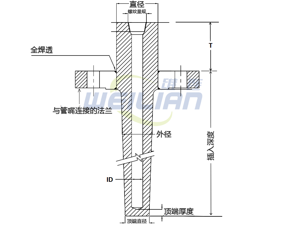
Flanges and welding designs are shown below. It is better to provide a sketch of the thermowell with the required specifications when making an inquiry. The sketch shall include tip diameter, tip thickness, well ID, taper length, unsupported diameter, instrument connection details, etc.

General specification of thermal sleeve
It should cover the following minimum aspects.
TW should be at least one SS316 (different materials can be used according to the service). Sometimes it is not allowed to weld dissimilar metals of flanges and thermal sleeves. Sometimes, specific requirements require hardening of the thermowell. Case hardening thickness and case hardening are important for immersion length.
Lined/sleeved thermowells are an economical solution for chemically corrosive fluids. The base material can be SS316. However, depending on the fluid, Hastelloy-C, nickel, titanium, tantalum and silver can be selected as the lining. This will provide the strength of the stainless steel and the corrosion resistance of the lining.
Particular care should be taken when selecting the correct thermowell design and material for high temperature applications. The supplier should be consulted for temperature measurements, e.g.>900 o C
Sometimes "protective tubes" are used instead of thermowells to protect thermocouples. These protective tubes are usually made of ceramic materials and are installed in high-temperature flue gas and pipeline applications. Protective tubes can also be made of Inconel, and their ends are open to improve response speed and heat transfer speed.
TW shall be of tapered design and shall be drilled from solid bars.
The instrument connection of the thermowell shall be ½” NPT (F) – used for connection of temperature element in thermal sleeve.
The bore size of the thermowell shall be suitable for the outer diameter of the corresponding temperature element. For example for 6 mm OD sheathed RTD temperature sensors.
Flanged thermowells should normally be selected. The welded thermal sleeve can only be installed where the fluid velocity and density are high and the bending load is too high for the flanged thermal sleeve.
Thermowells are preferably mounted at 90 〜 from the tube axis. However, it is allowed to be installed at a position 45 ° to the pipe axis or on the pipe elbow.
When the thermowell is installed near the DP type flow transmitter (orifice element, venturi or pitot tube) or vortex flowmeter, sufficient distance shall be kept to avoid flow measurement error.
TW shall carry out dye penetrant test, water pressure test and hole concentricity test for welded joints. If applicable, the certification of the relevant authority shall be considered.
General guidelines for dimensions and lengths of thermowells
It is important to understand the difference between insertion length and immersion length.
Immersion length of thermal sleeve
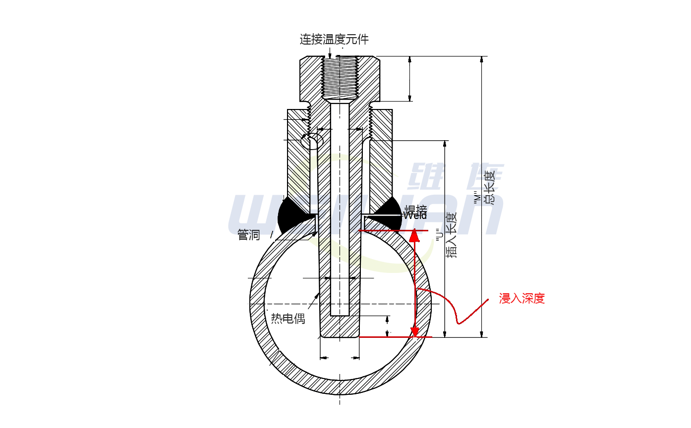
The immersion length of the thermal sleeve is the distance between the tip of the thermal sleeve and the immersion point in the measured medium. The standard symbol for the immersion length of the thermowell is "R".
热套管插入长度
热套管的插入长度是热套管尖端与(但不包括)其他连接到容器的装置的外螺纹之间的距离。热套管插入长度的标准符号是“U”。
插入长度“U”始终等于或大于热套管的浸入长度“R” 。
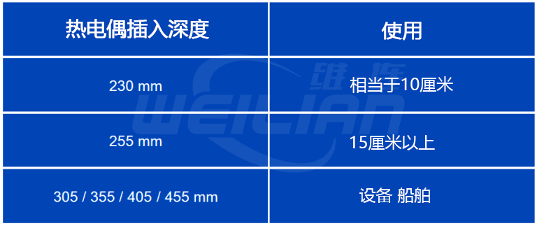
API RP 551:垂直于管壁安装的 TW 的最小浸入长度应为 5厘米。
一般的经验法则是使用至少等于热套管直径 10 倍的浸入长度。
一些客户根据管道尺寸对插入长度有特定要求或标准要求。例如 DEP 31.38.01.11-Gen。
一些客户指定热套管尖端应在管道 ID 的 1/3 和 2/3 之间或容器 ID 的 1/2 之间,以获得更好的温度精度。
热套管长度
法兰型设计的热套管总长度可通过以下详细信息计算得出:
☻喷嘴颈部长度
☻绝缘厚度
☻最小插入长度要求
如果根据 PTC 19.3 的热套管尾流频率计算失败,则可以执行以下操作。
☻在指定的标准范围内增加根部和尖端直径。但是,这可能会导致响应时间延迟。
☻U 长度减少(但是,保持 API RP 551 和/或合同规范规定的最低要求)
☻减少喷嘴颈部长度(例如 200 毫米到 150 毫米)
☻考虑列式设计的热套管
☻增加喷嘴的尺寸(例如 30mm 到50mm法兰)

