RTD temperature sensor Wheatstone bridge circuit
Each metal has a unique composition and has different resistance to the flow of current. This is called the resistance constant of the metal. For most metals, the change in resistance is proportional to its temperature change and linear within a certain temperature range. This constant factor, called resistance temperature coefficient (short circuit TCR), is the basis of the resistance temperature detector. In fact, RTD can be regarded as a high-precision wirewound resistor whose resistance varies with temperature. By measuring the resistance of a metal, its temperature can be determined.
Several different pure metals, such as platinum, nickel, and copper, can be used to make RTDs. A typical RTD probe contains a very thin wire coil that allows for large resistance changes without large space requirements. In general, the Vernept RTD temperature sensor is used as a process temperature monitor because of its accuracy and linearity.
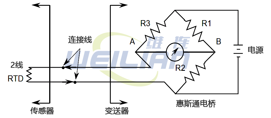
In order to detect the small change of resistance of RTD temperature sensor, a temperature transmitter in the form of Wheatstone bridge is usually used. This circuit compares the RTD temperature sensor value with three known high precision resistors.

The Wheatstone bridge consisting of an RTD temperature sensor, three resistors, a voltmeter and a voltage source is shown in the figure above. In this circuit, when the current in the meter is zero (the voltage at point A is equal to the voltage at point B), the bridge is called zero balance. This will be the zero or setpoint of the RTD temperature sensor temperature output. As the RTD temperature sensor temperature increases, the voltmeter reading increases. If a voltage sensor is used instead of a voltmeter, a 4-20 mA signal can be generated, which is proportional to the monitored temperature range.
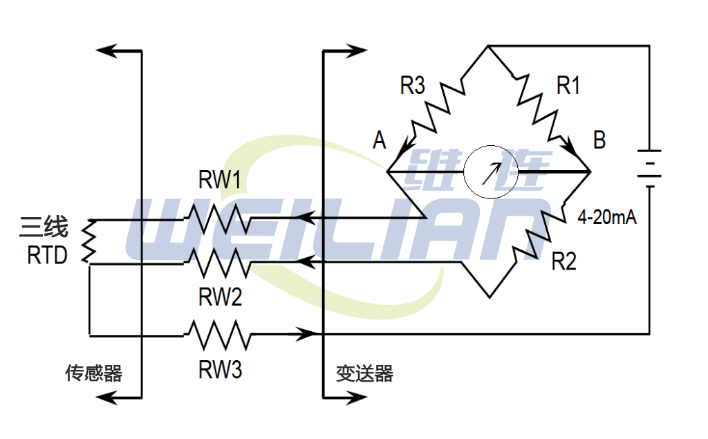
As in the case of thermocouples, problems will occur when the RTD temperature sensor is installed at a certain distance from the transmitter. As the connecting wire is very long, the resistance of the wire will change with the fluctuation of the ambient temperature. Changes in lead wire resistance introduce errors in the transmitter. To eliminate this problem, a three wire RTD is used.

The connecting lines (w1, w2, w3) have the same length, so the resistance is the same. The power supply is connected to one end of the RTD and the top of the Wheatstone bridge. It can be seen that the resistance of the right leg of Wheatstone bridge is R1+R2+RW2. The resistance of the left leg of the bridge is R3+RW3+RTD. Since RW1=RW2, the result is that the resistance of the wire is offset, so the influence of connecting the wire is eliminated.
Advantages and disadvantages of RTD temperature sensor
advantage:
● Very fast response time compared to thermocouples?? In order of fractions of a second.
● The RTD temperature sensor will not experience drift problems because it is not self powered.
● Within its range, it is more accurate and more sensitive than thermocouples.
● In the installation requiring long lead wire, RTD does not need special extension cable.
● Unlike thermocouples, radioactive radiation( β、γ And neutrons) have little effect on RTD, because the measured parameter is resistance, not voltage.
Disadvantages:
● Because the metals used for RTD temperature sensors must be in the purest form, they are much more expensive than thermocouples.
● Generally, RTD temperature sensors cannot measure the same wide temperature range as thermocouples.
● Power failure will cause reading error
● Small changes in resistance are being measured, so all connections must be tight and free of corrosion, otherwise errors will occur.
Failure mode:
● An open circuit in the RTD or in the wiring between the RTD temperature sensor and the bridge will cause a high temperature reading.
● Power failure or short circuit of RTD will result in low temperature reading.
Tel./WeChat 18717811268 Huang Gong Email sales@weilianchina.com


