
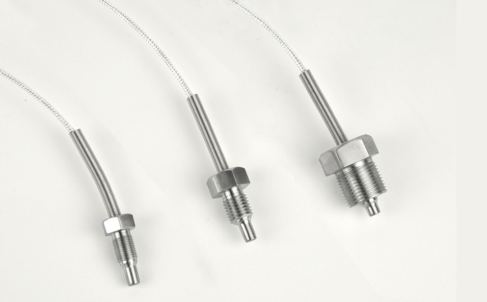
 Operating principle of resistance temperature sensor
Operating principle of resistance temperature detector (RTD)
Thermal resistance temperature measuring device
A change in temperature will cause a change in the resistance of the material. Measure the resistance change to infer the temperature change.
There are two types of thermal resistance measuring equipment:
● Resistance temperature detector (RTD)
● Thermistor
Resistance temperature detector
Resistance temperature detector (RTD) is basically a long and small diameter metal wire wound in the coil or an etched grid on the substrate, much like a strain gauge. Platinum is the most commonly used metal for RTD temperature sensors.
working principle
The working principle of resistance temperature detector (RTD) is that the resistance of metal will change predictably in a basically linear and repeatable way with the change of temperature. The RTD temperature sensor has a positive temperature coefficient (resistance increases with temperature). The resistance of the element at the base temperature is in direct proportion to the reciprocal of the length and cross-sectional area of the element.
The RTD temperature sensor is designed to measure the variability in the actual measurement of typical circuits with RTD temperature, and then used to calculate the temperature change. The resistance of RTD temperature sensor increases with the increase of temperature, just as the resistance of strain gauge increases with the increase of strain.
Bridge circuit construction
The figure below shows a basic bridge circuit, which consists of three known resistors R1, R2 and R3 (variable), an unknown variable resistor RX (RTD), a voltage source and a sensitive ammeter.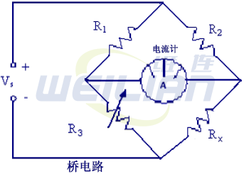
Resistors R1 and R2 are the ratio arms of the bridge. They ratio the two variable resistors of the current flowing through the ammeter. R3 is a variable resistor, called a standard arm, that can be adjusted to match an unknown resistor. The inductive ammeter visually displays the current flowing through the bridge circuit. The circuit analysis shows that when R3 is adjusted to make the ammeter reading zero, the resistance of both arms of the bridge circuit is the same. The relationship between the resistance of the two arms of the bridge can be expressed as
Since the values of R1, R2 and R3 are known, the only unknown value is Rx. When the ammeter is zero, the value of Rx can be calculated for the bridge. Knowing this resistance value provides a reference point for calibrating the instrument connected to the bridge circuit. The unknown resistance Rx is given by the following formula
RTD bridge circuit operation
A simple circuit is a quarter bridge Wheatstone bridge circuit, which is called a two-wire RTD temperature sensor bridge circuit here.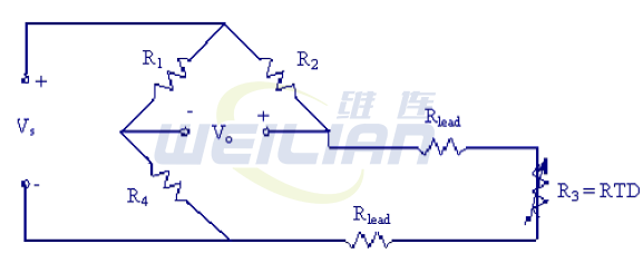
The R lead represents the resistance of one of the wires (called the lead) from the bridge to the RTD temperature sensor itself. In the strain gauge circuit, the lead resistance does not matter because the R lead remains constant.
However, for RTD temperature sensor circuits, some parts of the leads are exposed to changing temperatures. As the resistance of metal wire changes with temperature, R lead changes with T, which will cause measurement error. This error may be important - changes in lead resistance may be mistaken for changes in RTD temperature sensor resistance. In addition, the two wire RTD temperature sensor bridge circuit shown in the above figure has two leads, which doubles the error. An ingenious circuit designed to eliminate the lead resistance error is called a three wire RTD temperature sensor bridge circuit. The three wire RTD bridge circuit is shown in the figure below.
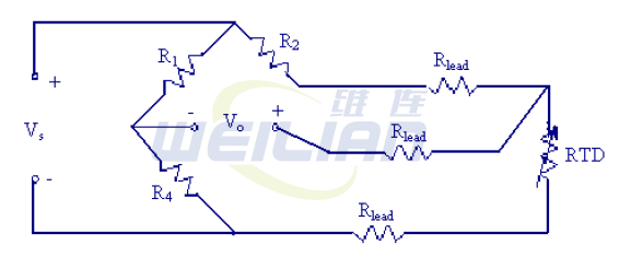
It is still a quarter bridge circuit because only one of the four bridge resistors is replaced by RTD. However, one of the leads has been placed on the R 2 leg of the bridge instead of the R 3 leg.
To analyze this circuit, assume that R 1=R 4, R 2=R 3 at the beginning, when the bridge is balanced. Recall the general formula of Wheatstone bridge:

Note that R 3 and R 2 have opposite symbols in the above equation. Therefore, if the lead resistances of pin 2 (top) and pin 3 (bottom) are the same, the lead resistances will cancel each other and have no net effect on the output voltage, thus eliminating the error.
What about the resistance R lead of the third lead of the middle conductor? Well, because V o is measured with an almost infinite impedance device, there is no current flow in the middle lead, so its resistance will not affect anything!
The following redrawn equivalent circuits may help explain the cause of lead resistance cancellation:
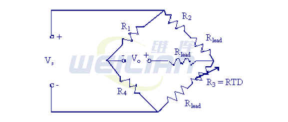
In the above figure, it is obvious that if the R lead changes equally in the second leg and the third leg of the bridge, its effect will be offset.
RTD Material and Structure
The function of RTD is a little like an electrical sensor, which converts temperature changes into voltage signals by measuring resistance. The most suitable metals for RTD sensors are pure metals or some alloys with uniform quality. Their resistance increases with the increase of temperature. On the contrary, the resistance decreases with the decrease of temperature. Only a few metals have the properties required for use in RTD components. The common materials used in RTD sensors are BALCO wire, copper and platinum.
● BALCO – The sensor constructed with BALCO wire is an annealed resistance alloy with a nominal composition of 70% nickel and 30% iron. The BALCO 500 ohm resistor element provides a relative linear resistance variation from – 40 to 250 °. The sensor is a lightweight device that can quickly respond to temperature changes. When 1000 ohms are measured through the BALCO element, the temperature is approximately 70 ° F. As the temperature increases, the resistance changes 2.2 ohms per 1 ° F. This is called the resistance temperature coefficient curve (TCR curve). In BALCO, the resistance is directly related to temperature, that is, with the increase of temperature, the resistance increases proportionally. The typical temperature measurement range of BALCO is - 40 ° to 240 ° F.
● BALCO – The sensor constructed with BALCO wire is an annealed resistance alloy with a nominal composition of 70% nickel and 30% iron. The BALCO 500 ohm resistor element provides a relative linear resistance variation from – 40 to 250 °. The sensor is a lightweight device that can quickly respond to temperature changes. When 1000 ohms are measured through the BALCO element, the temperature is approximately 70 ° F. As the temperature increases, the resistance changes 2.2 ohms per 1 ° F. This is called the resistance temperature coefficient curve (TCR curve). In BALCO, the resistance is directly related to temperature, that is, with the increase of temperature, the resistance increases proportionally. The typical temperature measurement range of BALCO is - 40 ° to 240 ° F.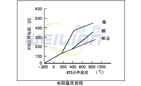
The copper and nickel versions operate in a lower temperature range and are cheaper than platinum. Platinum is the most versatile material because of its wide temperature range (– 200 ° C to 850 ° C), excellent repeatability, stability, and chemical and corrosion resistance.
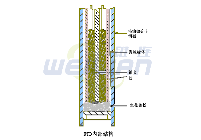
RTD components are usually long spring wires enclosed in a metal sheath by an insulator. The following figure shows the internal structure of the RTD.
This special design has a platinum element surrounded by a porcelain insulator. The insulator prevents short circuits between the wire and the metal sheath. Inconel is a nickel iron chromium alloy, which is usually used to manufacture RTD sheaths due to its inherent corrosion resistance. When placed in a liquid or gas medium, the Inconel sheath quickly reaches the medium temperature. Temperature changes can cause the platinum wire to heat or cool, resulting in a proportional change in resistance.
Advantages: resistance is linear with temperature, good stability, wide operating temperature range, interchangeable in wide temperature range
Disadvantages: the resistance changes little with temperature, and the response may be slow. Due to the influence of self heating, the transmitter may need three or four wire leads for lead resistance compensation, and external circuit power supply is required
Other facts
● RTDs are typically used to sense the temperature of air and liquids in pipes and ducts, and as room temperature sensors. The resistance of RTD elements varies with temperature. Some elements exhibit large resistance variations, linear variations, or both over a wide temperature range.
● The changing voltage at both ends of the sensor element determines the resistance of the sensor. The power supply provided for this purpose may cause slight heating of the element and may cause inaccurate temperature measurement. The self heating effect can be minimized by reducing the supply current or using components with higher nominal resistance.
● The resistance of some RTD elements is as low as 100 ohms. In these cases, the lead resistance connecting the RTD to the controller may significantly increase the total resistance of the connected RTD and may cause errors in the temperature measurement. For example, a sensor 25 feet from the controller has a copper control wire of 25 x 2=50 feet. If the DC resistance of the control wire is 6.39 ohms/ft, the total DC resistance of the 50 foot long wire should be 0.319 ohms. If the sensor is a 100 ohm platinum sensor with a temperature coefficient of 0.69 ohms/degrees Fahrenheit, a 50 foot wire will introduce an error of 0.46 degrees Fahrenheit. If the sensor is a platinum sensor with a temperature coefficient of 3000 ohms, 4.8 ohms per degree Fahrenheit, 50 feet of wire will introduce an error of 0.066 degrees Fahrenheit.
Therefore, the smaller the resistance of the sensor element, the greater the possibility of error. Significant errors can be eliminated by adjusting the calibration settings on the controller, or, if the controller is specifically designed for this purpose, a third wire can be connected to the sensor and connected to a special compensation circuit designed to eliminate the effect of lead length on the measurement

