National hotline
136-5182-6898


 Disadvantages of resistance temperature sensor
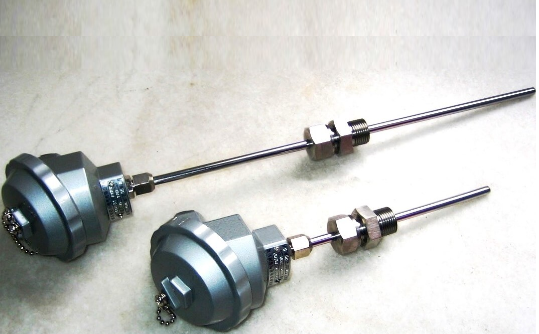
resistor temperature detector (RTD) is a sensor used to measure temperature. Many RTD temperature sensor components are composed of a section of the fine lines wrapped around ceramic or glass core, but also use other structures.
TheRTD line is a pure material, usually platinum, nickel, or copper.
The material has an accurate resistance/temperature relationship to provide temperature instructions. Because the RTD temperature sensor component is fragmented, they are usually installed in the protection probe.
The following is the main disadvantage of the resistor temperature detector:
Self -heating
When the current is applied to stimulate the RTD temperature sensor element to measure its signal, the thermal energy will be generated.
The self -heating may cause the temperature measurement error. Since the RTD temperature sensor changes its resistance according to the temperature, the most practical measurement is to allow the current through it and measure the voltage drop generated.
Unfortunately, this kind of incentive current through component resistance will increase the temperature of the component because it trys to dissipate this power through heat, thereby increasing our temperature measurement error.
The way to confront the positive transformation driven by self -heating is to increase thermal contact with the material we are sensing, and/or reduce the incentive current.
The self -heating ofRTD sensors is usually represented by MW/° C, which refers to the power required to increase the temperature of the internal component by 1 ° C. Therefore, the higher the number, the lower the self -heating.
For example, assuming a 2MA incentive current driver 100Ω platinum RTD temperature sensor at 100 ° C. This will generate a 138.5Ω sensor resistance. Its heating specifications are 50mW/° C, which moves in water at a speed of 1m/second.
Therefore, the calories generated by this configuration are 1000MW/w * i 2 * r = 1000 * (0.002a) 2 * 138.5Ω = 0.55MW.
This causes the self -heating error to be only (0.55mW)/(50mW/° C) = 0.01 ° C.
It should be noted that the effective self -heating of components depends to a large extent on its immersion medium.
For example, the self -heating ability of RTD temperature sensor in static air is 100 times that of flowing water applied to this specification.
Because we measure the resistance of the RTD temperature sensor by absorbing the current, the I 2 R power dissipated by the RTD temperature sensor will cause components to heat up.
Self -heating will change the RTD temperature sensor resistance and increase the measurement error.
By providing lower excitation currents, it can minimize the negative effects of self -heating.
Some instruments will minimize this error in the RTD temperature sensor incentive current as low as 0.1mA.
In the above example, this will reduce the self -heating to ~ 0.001MW/50mW/° C = 0.00003 ° C, which is insignificant even in the static air.
The size of the error is inversely proportional to the heat dissipation capacity of the sensor element. This is the product of its materials, structure and environment.
Small RTD temperature sensor components will have a higher self -heating effect because they have a small heat dissipation surface area.
Maybe the worst case is the film RTD temperature sensor, which usually has high thermal resistance and corresponding small heat dissipation surface area.
Usually, it provides a constant in the RTD sensor specification. This number is related to the power required to increase the temperature of the RTD by 1 degree.
Therefore, the dissipation constant of 25MW/° C indicates that if the power loss of I 2 R in RTD is equal to 25 mW, the RTD will heated 1 ° C.
Disposal constant is usually specified under two conditions: free air and full stirring oil bath. This is because the medium has different calories from the device.
The power and dissipation constant that can be dispersed from RTD can be obtained through the following formulas:
Δt = p/pd
Among them, the temperature rise caused by Δt = the unit is ° C; the power consumption in the RTD in P = circuit, the unit is W; the dissipation constant of PD = RTD, and the unit is W/° C.
Summary:
The maximum error of the ASTM standard requires that when 33 mW is applied to the 25 ° C water, the maximum error of IEC requires that the maximum error in the maximum working current at 25 ° C is 0.05 ° C.
These test methods are a good laboratory comparison method for PRT installed in the process of appropriate immersion. The working current is 1 ma or lower, so the power of 100 ω PRT (i 2 R) is also very small (0.02 - 0.39 mW).
In the sensor in the range of 500-1000 Ω, or when the process shows poor heat transfer conditions (such as static air or low-pressure gases), a large error may occur.
Thermal electromotive force or Syberg or thermoelectric effect
Maybe do you think the Syberg effect is only applicable to hot electric puppets ? But similar to the hot electric puppet , Platinum RTD is also made of two different metals -platinum RTD components and leading copper.
For some applications, these connections in the sensor circuit will generate a Belberry voltage, which can offset the IR voltage of the IR generated in the resistive element and slightly deviate from the reading.
For example, if the temperature gradient is allowed to generate along the sensor element, the node between the platinum sensor element and the copper line may generate a thermal voltage of about 7UV/° C.
For most applications, this small anti -electromotive momentum will not become an important source of error, but it will cause problems that run at a very high -precision measurement system running under low incentive current (maybe this may be to maximize the reduction Self -heating errors) -The conditions are usually only measured in the laboratory.
The material and structure of RTD make it a relatively large element, which also makes it difficult to use RTD to measure the temperature of a single contact point.
However, RTD provides an excellent way to measure the average temperature of the surface, which realizes this by distributed resistance wires on the surface area.
However, if this surface contact is also expanded to a certain distance, so that the connection of the lead at each end of the component is too far away, which may cause the Seabeck error. lead.
These errors can be prevented by carefully locating the sensor by using appropriate leads and carefully positioning sensors.
In short, different lead materials like copper can generate a T/C junction where it is connected to the platinum element, and then generate another T/C knot on the other end.
If the two nodes are at different temperatures, thermal electromotive momentum will be generated, which will affect the IR measurement of the RTD component.
If all knots are kept at a uniform temperature, the algebra and zero of thermal electromotive motivation in the circuit composed of any amount of different materials.
Therefore, you only have two remedial measures to fight this impact: either using the same material as the component (not practical, because this will be very expensive for platinum components with long lead), or just the temperature will just take the temperature Maintaining the same (that is, along the components) or almost the same, this will cause the contribution to the net motor for voltage measurement to be ignored.
Summary:
Thermal electromotive force error is also called the thermocouple effect. This error is caused by the wire connection of various wire components, material homogeneity, and the temperature gradient in PRT (RTD).
ASTM and IEC standards provide a guide to high -sensing current -although when the EMF impact is existing, it will have a greater impact at a lower current near the standard working current.
The error occurs mainly in the DC system. In order to minimize the hot EMF error, select PRT with low specified EMF.
In addition, the use of AC circuits and appropriate selected transmitters can eliminate the impact of electromotive momentum.
response time or time response
The time constant of RTD refers to the speed of the resistance of its component response contact temperature changes.
The fast time constant helps reduce the error in the measuring system that encountered rapid changes in temperature.
When we consider the structure of the RTD, we can infer that the response time will strongly depend on the quality of the sensor element and its insulation structure, as well as the heat transfer capacity of the sensing material.
This directly affects the rate of heat transmission from the external sensing surface to the core sensing element.
In contrast, because RTD measures temperature in a larger area, not small contact points like armocouple, and because the RTD sensing element must be insulated, its response time is much slower than the thermal puppet.
Similarly, compared with the same sensor directly immersed in the fluid, the RTD probe in the thermocouple sleeve reacts slower.
The response speed of a strong sensor internal connection is twice the sensor of a single loose interface in the same component.
Surface RTD will respond to the surface temperature change faster.
The response time of a given sensor is usually defined as the time required for the step jump of the sensor response contact temperature to 63% of the final value of its thermal equilibrium.
These times are usually measured in the water that flows in 1 meter/s (3 feet/s) and is measured in air that flows in 3 meters/second (10 feet/s).
Although it is not common, sometimes the response time refers to the time interval of Platinum RTD that reaches 90%(rather than 63%) of its final value.
When comparing the sensor type, you must pay attention to this difference.
Summary:
If PRT (RTD) cannot respond quickly enough to respond to temperature changes, it may cause errors related to time response during the temperature transient.
During the steady or close -state operation, the error is zero. ASTM and IEC do not define this error, although there is a test method that can represent the response time of PRT for comparison.
When monitoring the transient conditions are very important, you can minimize this error by selecting sensors with a faster laboratory testing time and evaluating the relevant changes to the time response performance of the optimal matching sensor.


