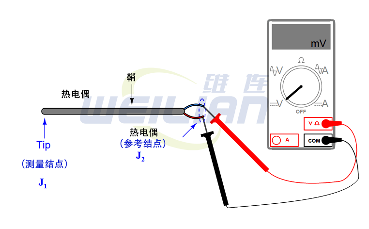
 Manually explain thermocouple voltage
The voltage indicated by the voltage meter connected to the thermocouple is the difference between the voltage generated by the measurement of the measurement (the point of the two different metals in the position of the location of the sensor temperature). Table line):
V Table = v J1 2 v J2
This makes the thermocouple puppet essentially a differential sensing device: they generate the measured voltage that is proportional to the temperature difference between the two positions. The inevitable facts of the thermocouple circuit complicate the task of any voltage measurement value obtained from the thermocouple of the thermocouple. In order to convert the voltage measurement value generated by the voltage meter connected to the thermocouple, we must add the voltage generated by the measurement node (V J2) to the voltage indicated by the voltage gauge in order to produce the voltage generated by the measurement node (V J1 To. In other words, we handle the previous equations into the following forms:
V j1 = v j2 + v table
We can determine the reference node voltage by placing a thermometer near this node (the thermoelectric puppet connection to the position of the voltage meter testing lead) and refer to the temperature of the thermocouple type and the corresponding voltage thermoelectric puppet table. Then, we can take the voltage of V J1 and refer to the same table, and find the temperature value corresponding to the calculated measurement of the measurement of the measurement. The form released by the National Institute of Standards and Technology (NIST) shows the type of composition voltage and temperature of the standardized thermocouple type. Although the voltage of the thermocouple node can be used in the same way as the resistance of the RTD, the function of the thermocouple node is not as good as the RTD function. Therefore, in actual use, the table is very popular.
Also check: thermocouple table
To illustrate this, suppose we connect the voltage meter to the K -type thermocouple and measure it to 14.30 millivol. The thermometer located near the thermal puppet/voltage meter connection shows the ambient temperature of the 73 Brigade. The voltage meter of the K-type thermocouple (in this example is the NIST "ITS-90" reference standard), we see that the K-type knot of 73 Hualhi corresponds to 0.910 millivolttrasion. Add this number to our instrument measurement value of 14.30 millivoltors, and we draw that the total of the measurement ("heat") knot is 15.21 millivol. Back to the same numerical table, we saw that 15.21 millivolo fell between 701 and 702. Linear interpolation between table values (701 O F is 15.203 MV, and 702 o is 15.226 MVF), we can more accurately determine that the measurement node is 701.3 Fahrenheit.
Manually perform voltage measurement, reference the millions value table, execute addition, and then refer to the process of reference to the same table is quite boring. The compensation reference knot inevitably appear in the thermocouple circuit is what we have to do, but this is not a thing that must always be done by others. The next section discusses the influence of the automatic compensation reference end, which is the only practical alternative of the temperature instrument based on the continuous thermocouple.

