RTD temperature sensor's lead compensation technology
RTD temperature sensor is usually called PT100 temperature sensor) is one of the most commonly used temperature sensors in the industry. As we all know, it is the most accurate and repeated sensor for low-to-medium temperature (-300 to + 600 ° F).
RTD represents a resistance temperature device. It is very simple. The sensor is composed of a resistance value with temperature. So far, the most common RTD temperature sensor is PT100 385. This component is 100 ohm at 0 ° C (32 ° F) and 138.5 ohm at 100 ° C (212.0 ° F).
One of the biggest challenges faced by instrument engineers is to deal with the problems of relatively low equipment resistance. This is because any of the biased resistors (especially the lead resistance) of the RTD temperature sensor component will increase the measured resistance to the measured resistance significantly.
In order to solve this problem, different lead compensation schemes were invented, and they were called 2 lines, 3 and 4 lines.
2 line technology
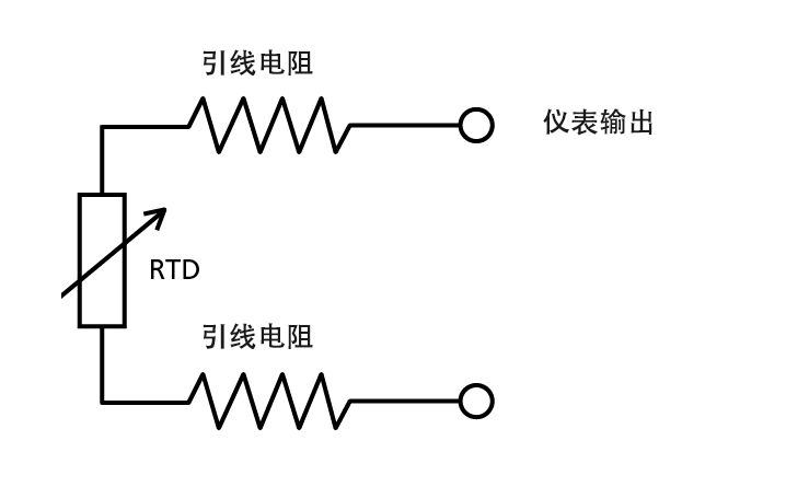
2 Line RTD temperature sensor Two -line RTD temperature sensor is the simplest form.
The lead R is the lead resistance of the RTD to the wire of the instrument. In this case, the instrument will read a higher temperature than the real RTD, because the instrument measurement:
RTD + 2X lead R
For example, if the wire resistance is 0.5 ohm, the number of instruments will be 2.6˚C (4.7F) higher than the due. The only way to compensate this error is to manually adjust the offset of the instrument. Of course, this becomes boring and prone to artificial errors. Automatic lead compensation instruments are invented to solve this problem. Compensation technology uses additional wires connected to the sensor to measure the lead resistance and eliminate its impact.
3 line technology
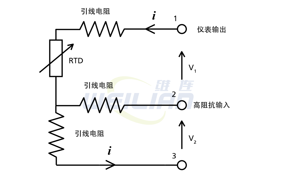
The three -line leading scheme requires two measurement. The first measurement is V1, which gives the result of RTD + Lead R. The second measurement was given the result V2 of R Lead. Therefore, to obtain a real RTD measurement value, we only need to subtract VLEAD from VLEAD + RTD to leave the RTD.
Therefore, for any lead R value, this solution will automatically compensate the lead resistance and provide you with the right temperature.
The assumption of this technology is that the lead resistance of each wire in the three wires is the same. This is a very safe assumption, especially modern manufacturing technology used in wire production. In the actual example, you will know more about how these errors are superimposed.
4 -line technology
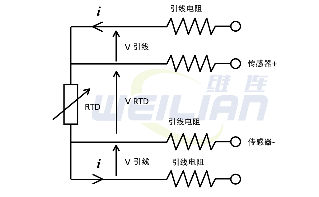
This technology depends on the very high input impedance of modern instruments, so there is almost no current flow in the sensor wire: this is a very effective assumption today.
By measuring VRTD in one measuring, RTD can be felt in the scheme errors. The advantage of this scheme is that it can also compensate for any lead imbalance.
Historically, the 4 -line technology is popular in Europe by the absolute accuracy of Germany in Europe.
In the North American market, the 3 -line technology has been widely used in the past. Even today, the sales volume of 4 -line sensors exceeds the 4th line sensor by 3 to 1. This is dominated by cost and practicality.
Practical examples
1. The headset transmitter uses a 24 AWG wire to connect the RTD sensor to a transmitter with a length of 12 inch
picture
2. The headset transmitter uses a 24 AWG wire to connect the RTD sensor to a transmitter with a length of 12 inch
picture
From the results of the above -mentioned head -wearing applications, both 3 and 4 are excellent technologies to eliminate the effect of the lead resistance.
In addition, the long cable test also shows that 3 to 4 wires are enough. Even if there are some wireless wires, the calculated error is placed in the uncertain range of almost all industrial applications.
Another question that sometimes asked is: "If I have a 4 -line RTD, can it be used as a 3 -line RTD?" The wire guide line compensation system increases any errors.
However, it is not.
You cannot use the 3rd and fourth lines of the instrument to use the 3 -line RTD with the 4 -line instrument together with the 3rd and fourth line on the instrument. This will lead to a significant binding resistance error.
In summary
It should be completely avoided using the 2 wire RTD input, unless the length of the wire is short and you use a low -standard wire to reduce the lead resistance.
Over the years, 3 lines and 4 -line compensation technologies have proven to provide a good way to compensate the lead resistance in RTD.
If you care about the absolute accuracy of the length of the long lead, you will choose 4 lines. It turns out that the 3 -line technology is accurate to all actual industrial uses, and compared with the 4 -line technology, it can save about 20% of the cost.

