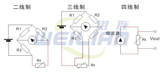
Platinum resistance Third Line system Four Line system wiring diagram
Comparison of platinum resistance sensor second -line system,
platinum resistance sensor three -line system ,
platinum resistance sensor four -line system The characteristics and application of the platinum resistance temperature measurement
Platinum resistance sensor structure:
Two -wire system: The resistance change value of the platinum resistance sensor and the connection wire resistance value together constitutes the output value of the sensor. Due to the additional error caused by the wire resistance, the actual measurement value is high. At the same time, the length of the wire should not be too long.
Three -line system: The three wire cross -sectional and length of the three wires caused by the platinum resistance sensor are the same. The circuit that measures the platinum resistance is generally unbalanced bridge. A power end of the bridge, the remaining two bridge arms where the platinum resistance is located and the adjacent bridge arm. When the bridge road balances, the change of the wire resistance is not hindered by the measurement result. The measuring error caused by the wire resistance of the wire line must be eliminated, but it must be a allocated bridge, otherwise it will not fully eliminate the obstacles of the wire resistance.
Adopting the three -line system will greatly reduce the additional error caused by the wire resistance, and the three -line connection method is generally adopted in the industry.
Four -wire system: When the measured resistance value is extraordinary, the resistance of the test line is probably introduced significantly errors. Two additional test lines are used to provide constant current with two additional test lines. Under the condition that the voltage meter input impedance is high enough, the current almost does not flow through the voltage meter, so that the voltage drop on the unknown resistance can be accurately measured. The defined. The current output type
transmitter is converted to the 4 ~ 20mA current output, and the external power supply must be powered by the external power supply.
The most classical type is that the transmitter requires two power cords, plus two current output cables, which must be connected to a total of 4 lines, called a four -wire transmitter.
Of course, the current output can be used as a public use of the power supply (public VCC or GND), which can save a line called a three -line transmitter.
In fact, everyone pays attention to it. The 4-20mA current itself can supply power to the transmitter, as shown in Figure 1.
The transmitter is equivalent to an extraordinary load in the circuit. The extraordinary thing is that the power consumption current of the transmitter changes between 4 and 20mA according to the output of the sensor.
The display instrument only needs to be stringed in the circuit.
This transmitter only needs to connect 2 lines, so it is called the two -line transmitter.
The lower limit of the industrial current ring standard is 4mA, so as long as it is within the range, the transmitter has at least 4mA power supply.
This makes the design of the two -line sensor.
In industrial applications, the measurement points are generally on the scene, and the display device or manipulation equipment is generally on the manipulation room or the cabinet.
The distance between the two is about tens to hundreds of meters.
Calculated at a 100 -meter distance, saving 2 signal transmission wires means a reduction in cost nearly 100 yuan! In addition, the fourth -line transmitter and the third -line transmitter must be shared with expensive shielding materials from the asymmetry of the wires in the wires.#1
Line, and the two -line transformer can use extraordinary cheap twisted wire wires, so the two -line transmitter in the application must be the first choice.
In the thermal resistance, there are two -line, three -line, and four -line system and two -line system. There are no line resistance compensation. The wiring is simple, but it must be brought into the additional error of the lead resistance.
Therefore, it is not applicable to the thermal resistance of the A -level accuracy, and the lead and the wire should not be too long during use.
The three -line line resistance compensation can eliminate the obstacles of the lead resistance, and the measurement accuracy is higher than the 2 line system. As a process detection element, its application is the most widely used.
Four -wire system: The method of connecting two wires at both ends of the thermal resistance root is called the four -line system. Two of them provides constant current I for the thermal resistance, convert R to voltage signal U, and then via the other two leading wires. Draw U to PLC.
This leading method can completely eliminate the resistance of the lead, but the cost is high, and it must be used for high -precision temperature detection.
There are also two -line and four -line systems in the transmitter, sensor, and flow meter. The four-line system is separated from the power supply and signal. For example, a high-power transmitter, 220VAC supply power to the transmitter, the differential transformer converts the micro-position signal to an electrical signal, the amplifier plate is converted to the constant current of 0-10mA The source is sent to the second instrument or DCS system, and now it is almost eliminated. Question: In the performance parameters of the pressure difference/force sensor and flowmeter, output signals often appear: second -line system (4-20) MA, third -line system (0 ~ ~ ~ 10) MA.


