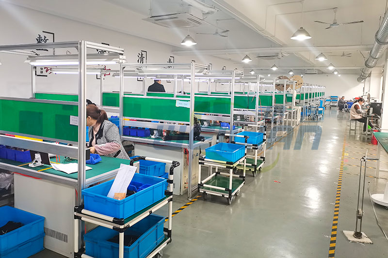
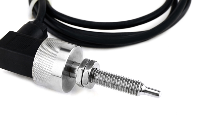
During the manufacture of thermocouples, care must be taken to ensure that there are no contaminants, and in the case of MIMS, there is no moisture before the thermocouples are sealed. TIG welding technology is used to ensure that no pollutants are generated during welding. Oxygen free welding can be realized by using argon protection to ensure that scaling and oxidation will not occur. If MIMS thermocouples are being manufactured, it is also good practice to weld thermocouples with the same material as the housing. The moisture can be eliminated by placing the thermocouple in an oven or heating the thermocouple with an oxygen torch to ensure that any moisture in the magnesium oxide insulation has been removed. These techniques are used for hot joints. In addition, the cold end must also be protected to prevent pollutants from entering, that is, the cold end should be placed in a suitable enclosure to prevent foreign gases, particles and moisture from entering
There are basically three types of hot connectors: • exposed • grounded • ungrounded
The selection of hot contacts will depend on the response of thermocouples, pollution hazards, physical constraints and electrical grounding considerations
Base metal thermocouple Base metal thermocouple is made of base metal element alloy (iron, copper and nickel). Basic metal thermocouples conforming to ANSI standards include e, j, k, n&t, which are generally used at temperatures below 1200 ° C.
Rare metal thermocouples These thermocouples are commonly referred to as "precious metal" thermocouples and are usually used for thermocouples with conductors made of platinum and/or platinum alloys. They are mainly composed of b type and r&s type, which are usually used for high temperature applications above 1200 ° c.
The development of mineral insulated thermocouples in sheath materials and integral sheath/element combinations allows the use of k&n thermocouples to achieve higher temperatures. Mineral insulated thermocouples can be classified as modern development. Mineral insulated metal sheath (MIMS) thermocouples came out 50 years ago, bringing revolutionary changes to the temperature measurement industry. It provides a compact design where elements are packaged in a protective environment.
Basic principle of thermocouple temperature sensor
Service life of thermocouple temperature sensor
Useful thermocouple life is a very difficult prediction, even if most details of the application are known. Unfortunately, such information is often difficult to determine. For any application, the best tests are to install units, use, and evaluate the in use performance of a design that is considered likely to succeed. The recommendations and non recommendations listed in the thermocouple type description are a good place to start when selecting the assembly style to be installed in the process for the first time
thermocouple temperature sensor offset and drift
Stability
All thermocouples are subject to calibration drift and use, which is only a matter of how much and how quickly it may occur. The performance of thermocouple depends heavily on the absolute uniformity of physical and chemical properties of the whole circuit length. When producing thermocouple materials, careful steps should be taken to ensure that this uniformity (or homogeneity) is achieved. During use, different parts of the circuit will experience different heat, chemical exposure and other conditions, so the physical structure and composition of these parts will change from the original thermocouple wire
Since the thermoelectric EMF generated by a given temperature difference is very sensitive to changes in the chemical and metallurgical properties of the wire, under the same conditions, the total EMF generated by the used probe may be different from that generated by other identical new probes. During the observable time, these changes are usually small (usually small enough to be negligible). However, under unfavorable conditions, it is possible to achieve large drift speed quickly
In order to achieve long-term reliable thermocouple life, the usual strategy is to operate the equipment comfortably at the highest temperature and provide it with the cleanest possible working environment. Enclosures, such as sheaths, protective tubes, and thermowells, are common methods of controlling the environment around thermocouples themselves
What will happen
Protective tubes, sheaths, and even thermowells may fail due to corrosion or mechanical damage. The processing process may exceed the temperature, exposing the thermocouple to an environment higher than the expected temperature. If the output of the sensor controlling a process is low, the process responds to its controller and may be forced to reach a temperature higher than expected. Base metal components are vulnerable to a few chemicals. They can also be changed by adverse operating conditions. In the case of supply, the content of impurities in high-quality precious metal thermocouple wires is very low. Therefore, it is easy to be polluted by the factors that can affect its thermoelectric performance. Platinum is particularly sensitive to the presence of free silicon. It can combine with free silicon to form eutectic alloys, which will melt at or below the normal service temperature. The protection tubes of high-purity insulators and precious metal components, as well as the cleaning during operation, are essential to prevent this situation
Human error may also be an influencing factor. The control may be set incorrectly, the connection may be incorrect, and the operating conditions of the inappropriate action response may be wrong. The compensation and correction of instruments and meters is a common means to deal with such errors
Troubleshooting thermocouple temperature sensor
方法
To evaluate the problem, check whether the system performance meets the conditions: Do changes in controls produce logical results? How about the product? Does its condition conform to the instrument description
How to test the used thermocouple temperature sensor
First, it is not always practical to remove the suspect thermocouple from service and "test" it in another place. Once the device is used, it means that it may no longer be homogeneous. Placing an uneven thermocouple under a set of different temperature gradients, even if it is slightly different, will result in different outputs and readings. Recalibrating a used thermocouple will certainly generate a number, but this number may not be meaningful in the place where the thermocouple is used
The best way to evaluate used thermocouples is to "detect" their position by placing a new thermocouple with a known output, and place suspect thermocouples during operation, and then compare readings. It is not practical to install two sensors at the same time. Remove the suspect probe and replace it with another probe with known good performance. Then, if the good probe and the removed probe are placed in the same place, and the process has not changed during the exchange, the readings of the two probes can be compared
Note that there is no need to reserve and use an unlimited number of new probes for these tests. Some suitable replacement equipment can be kept available, and one can be selected for testing. Under normal conditions, the drift or degradation of thermocouples is a gradual and very slow process. Therefore, a single replacement probe can be used multiple times to detect a process and is considered reliable for multiple repeated tests. Moreover, when a drifting detector is found, the test detector can simply remain in place as a working sensor, while the next substitute becomes the test equipment
System test
A useful instrument troubleshooting thermocouple system is a portable temperature indicator. Many of these devices can use two or more different types of thermocouples, and some provide output functions that can generate electrical output to simulate thermocouples operating at any selected temperature
In use, the instrument is usually connected to the wire of the circuit and tested at a convenient access point, such as a connector. Care should be taken to ensure that the correct polarity is maintained. In Australia, we use ANSI color codes where the negative is always red. There, the output of an operational sensor can be monitored and evaluated. Alternatively, using the "output" function of the instrument, an analog thermocouple signal may be sent back to the permanent indicator or controller of the circuit to verify the normal operation of the remaining circuits. When driving the signal back to the instrument, it is usually necessary to disconnect one side of the circuit to avoid the low resistance of the thermocouple itself "loading" the portable tester
The extension wiring part in the thermocouple circuit can also be checked for correct connection with a portable tester. The part under test should be electrically isolated from the rest of the circuit, and one end of a pair of extension wires should be shorted together. If the tester is connected to the other end of the short circuit pair, the tester should display the approximate temperature of the short circuit pair. Note that if both ends of the extended pair happen to be at the same temperature, it may be necessary to heat the shortened end slightly and verify that the tester has correctly seen the temperature change. The possibility of incorrect reverse connections is being checked in this test
From the development and planning of new projects to the transformation or upgrading of existing facilities, pyrotechnic sales engineers can be consulted. Our employees are here to help and advise you to ensure the best results and value. We would be happy to visit customers on site or hold meetings in our office
The main products of Weilian Electronics are thermistor sensors, RTC, NTC, transmitters, digital instruments, etc. Weilian Electronics is an electronic component brand integrating R&D, design, production and sales. The product has passed the IATF16949 (2016) quality management system certification and CE certification
has more than 20 years of experience in the electronic industry, and has long-term cooperation with colleges and universities; Parameters and dimensions can be customized according to customer requirements, focusing on the special needs of customers (electromechanical cooperation, electronic product transformation and upgrading, scheme provision, etc.).


 What are thermocouples and how they work?

