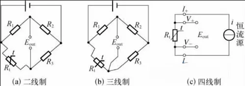
There are three lead modes of thermal resistance: two-wire system, three wire system and four wire system:
Two wire system
The two-wire system is to connect a wire at both ends of the thermal resistance. This lead is simple and cheap. However, the lead resistance becomes an arm of the bridge, which will bring additional errors. Only when the lead resistance is sufficient, its impact can be ignored. In the industrial field, the lead of thermal resistance is often very long, so it cannot be ignored generally.
Three wire system
The three wire system is that one wire is led out at one end of the thermal resistance and two wires are led out at the other end. When the thermal resistance is matched with the measuring bridge, the lead resistance is connected to the two arm lines of the bridge respectively, eliminating the influence of lead resistance and improving the measurement accuracy. This connection method is commonly used for industrial thermal resistance temperature measurement.
Four wire system
The four wire system is to connect two wires at both ends of the thermal resistor, two of which provide the current source for the thermal resistor. The voltage drop generated on the thermal resistor is connected to the potential measuring instrument through the other two wires. If the input impedance of the potential measuring instrument is high enough (the current is very small), the influence of the lead resistance can be completely eliminated. This connection mode is mainly used for high-precision temperature detection.
Pt100, that is, its resistance value is 100 ohms at 0 degrees. PT100 temperature sensor is a resistance temperature sensor made of platinum (Pt), which belongs to positive resistance coefficient. The relationship between resistance and temperature change is as follows: R=Ro (1+ α T).
PT100 thermal resistance three wire connection method
PT100 platinum resistance sensor has three leads, A, B, C (or black, red, yellow) can be used to represent the three wires, and the following rules exist between the three wires:
The resistance between A and B or C is about 110 ohm at room temperature, 0 ohm between B and C, and B and C are directly connected internally. In principle, B and C are no different.
Three wire wiring method
3-wire and 4-wire connection method of thermal resistance: 2-wire, 3-wire and 4-wire are adopted, which is mainly determined by the secondary instrument used.
Generally, three wire connection method is provided for the display instrument. One wire goes out of one end of PT100, and two wires go out of the other end, both of which are connected to the instrument. The resistance of the wire inside the instrument is offset by a bridge.
Generally, PLC has four wires, with two wires at each end, and two are connected to PLC output constant current source. PLC measures the voltage on PT100 through the other two to offset the wire resistance. Four wires have the highest accuracy, three wires can also be used, and two wires have the lowest accuracy. The specific usage should consider the accuracy requirements and costs.
Reasons for three wire connection mode
The resistance value of PT100 thermal resistance is 100 Ω at 0 ℃, and the resistance change rate is 0.3851 Ω/℃. Because of its small resistance value and high sensitivity, the resistance value of the lead cannot be ignored. The three wire connection method of thermal resistance can eliminate the measurement error caused by the lead line resistance. The principle is as follows:
The section area and length of the three conductors from the PT100 thermal resistor are the same (r1=r2=r3). The circuit for measuring the platinum resistance is generally an unbalanced bridge. The platinum resistance (Rpt100) is used as an arm resistance of the bridge. One (r1) of the conductor is connected to the power supply end of the bridge, and the other two (r2, r3) are connected to the arm of the bridge where the platinum resistance is located and its adjacent arm. In this way, the lead resistance of the same resistance is introduced into both arms, and the bridge is in a balanced state, The change of lead wire resistance has no effect on the measurement results.


