
The correct connections of all three types of RTD sensors (2-wire, 3-wire and 4-wire) to user configurable transmitters are shown below:
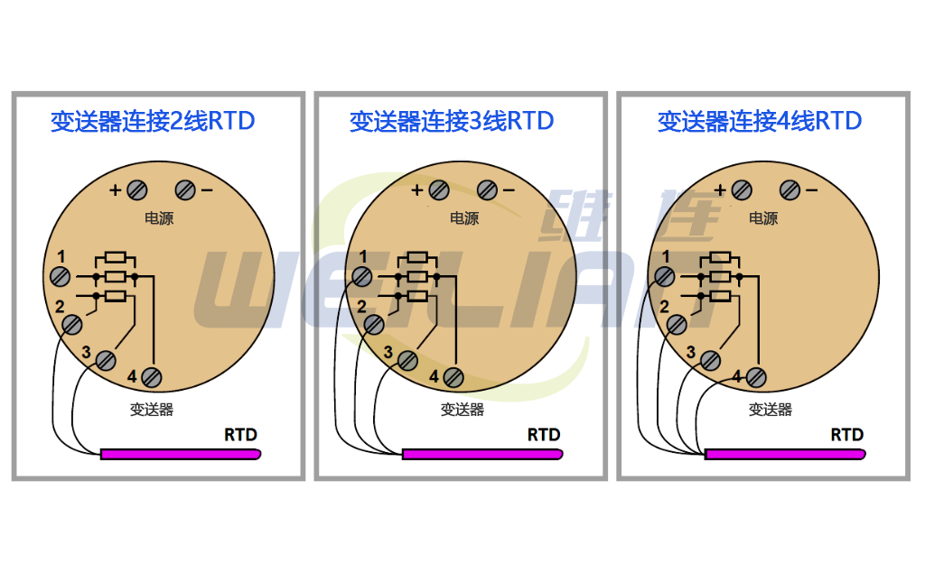
It is important to note that the common connection shown in the symbols of the 3-wire and 4-wire RTD temperature sensors represents the connection point at the sensor; It is not a jumper terminal for technicians during installation, nor is it an internal jumper inside the transmitter. The overall purpose of using 3-wire and 4-wire RTD temperature sensor circuits is to eliminate errors caused by voltage drop along the current carrying line, which can only be achieved when the "sensing" line extends to the RTD itself and is connected there. If the sensing terminal of the transmitter is only jumpered to the current carrying terminal, the transmitter will sense the RTD voltage drop plus the upper streamline voltage drop, resulting in an incorrect high temperature indication.
Unfortunately, misconceptions about the correct RTD temperature sensor connection abound among students and industry professionals at work. If you are lucky, the following demonstration will help you avoid such errors, and more importantly, help you understand why the correct connection is the best.
Always keep in mind the purpose of the 3-wire or 4-wire RTD temperature sensor connection: avoid inaccuracies caused by the voltage drop along the current carrying wire. The only way to do this is to ensure that the sensing (non current carrying) wire extends from the transmitter terminal to the sensor itself. In this way, the transmitter can "view" the voltage drop of the current carrying wire to "view" the voltage drop caused only by the RTD temperature sensor itself.
The following figure shows the correct and incorrect way to connect a 2-wire RTD temperature sensor to a 3-wire or 4-wire transmitter:
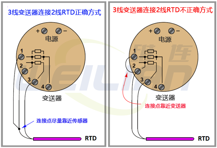
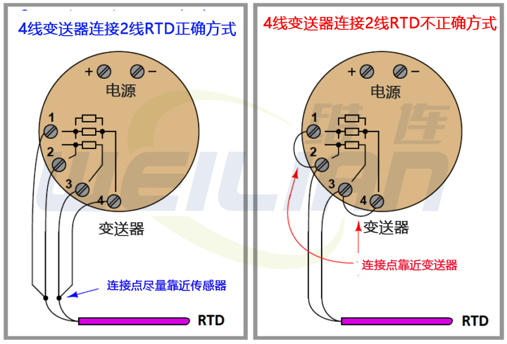
The jumper placed on the transmitter terminal violates the purpose of the 3-wire or 4-wire function of the transmitter, reducing its performance to that of a 2-wire system.
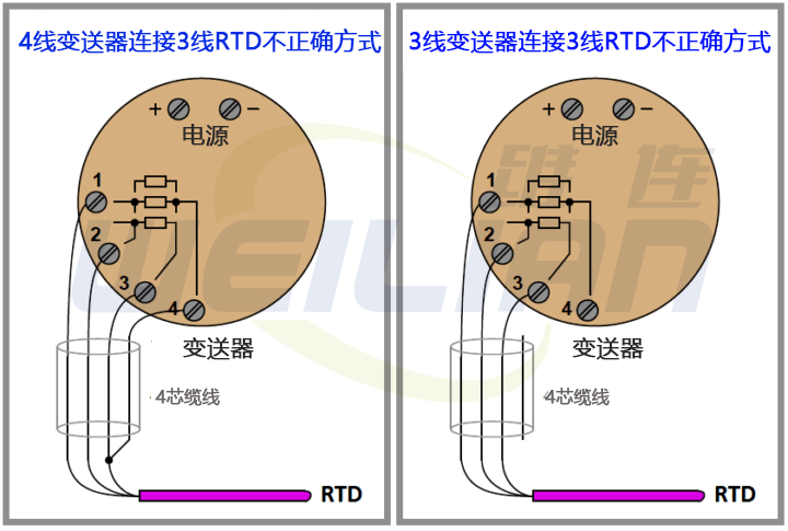
When someone tries to connect a 3-wire RTD temperature sensor to a 3-wire transmitter using a convenient 4-wire cable, a similar problem occurs:
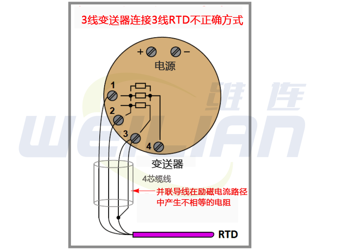
The 3-wire RTD temperature sensor measurement is based on the assumption that the two current carrying conductors have exactly the same resistance. By paralleling two of the four wires in a 4-wire cable, you will create unequal resistance in the current path, resulting in measurement error of the transmitter (Note).
Note: These errors can only be caused when parallel wires carry current. If you happen to connect the sensor terminal of the transmitter to the RTD (the one without current) with two parallel wires, it will not cause an error.
However, many RTD temperature sensor transmitters do not record which terminals are induced (no current) and which terminals are excited (current is sent to RTD), so if you just guess, you may make an error.
Since there is no real benefit in connecting the sensing terminal of the temperature transmitter to the parallel wire of the RTD, my suggestion is to use all four wires and configure the temperature transmitter to the 4-wire mode, or not use the fourth wire at all.
Better solutions for 3-wire RTD and 4-wire cable solutions include configuring the temperature transmitter as a 4-wire RTD input and actually using all four terminals (as shown on the left), or configuring the transmitter as a 3-wire RTD input without using the fourth wire in the cable (as shown on the right):
Photographs of modern temperature transmitters capable of receiving inputs from 2-wire, 3-wire, or 4-wire RTDs (and thermocouples, which are completely another type of temperature sensor) show the connection points and labels describing how the sensors work are connected to the appropriate terminals:
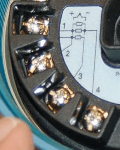
The rectangular symbol displayed on the label represents the resistance element of RTD. Symbols marked with "+" and "-" represent thermocouple nodes, which can be ignored in this discussion.
As shown in the figure, the two-wire RTD will be connected between terminals 2 and 3. Similarly, three wire RTDs will be connected to the common wires of RTDs with terminals 1, 2 and 3 (terminals 1 and 2 are the connection points of the two terminals). Finally, the four wire RTD will be connected to terminals 1, 2, 3 and 4 (terminals 1 and 2 are common terminals, terminals 3 and 4 are common terminals, on the RTD).
After connecting the RTD to the corresponding terminal of the temperature transmitter, the transmitter needs to be configured electronically for this type of RTD.
For this particular temperature transmitter, configuration is performed using a "smart" communications device that uses the HART digital protocol to access the transmitter's microprocessor-based settings. Here, the technician will configure the transmitter as a 2-wire, 3-wire, or 4-wire RTD connection.

