 Difference between 2-wire RTD temperature sensor, 3-wire RTD and 4-wire RTD
RTD temperature sensors (RTDs) are available in 2, 3, or 4 lead configurations. The best configuration for a particular application depends on a number of factors, but the sensor configuration must match the transmitter, otherwise the lead wire resistance cancellation circuit may not work.
Factors to consider:
Installation costs – more wires usually mean higher costs
Free space - more or larger wires require more space
Accuracy requirements – 2-wire configuration can provide the required accuracy, especially for high resistance components
RTD temperature sensor structure type:
2 Lead construction
3 Lead construction
4 Lead construction
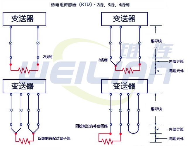
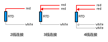
Thermal resistance wiring diagram
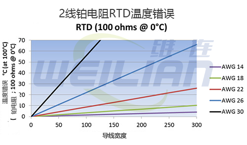
2 Lead wire structure 导致引线电阻增加到元件电阻。因此,温度读数人为地偏高。下图显示了 100°C 下 100 欧姆铂 RTD 的温度误差,来自不同尺寸和长度的 2 根引线。This causes the lead resistance to increase to the element resistance. Therefore, the temperature reading is artificially high. The following figure shows the temperature error of a 100 ohm platinum RTD at 100 ° C, from 2 leads of different sizes and lengths.
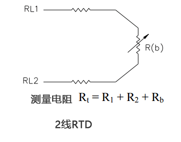
2-wire structure is 3 种类型中最不准确的,因为无法从传感器测量中消除引线电阻。2 线 RTD 主要用于短引线或不需要精确度的地方。The most inaccurate of the 3 types, because the lead resistance cannot be eliminated from the sensor measurement. 2-wire RTDs are mainly used for short leads or where accuracy is not required.
Only when the transmitter can measure the real 3-wire resistance, the 3-wire structure can eliminate the lead resistance error.
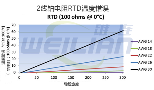
When all leads have the same resistance, lead resistance error elimination is most effective. Using three wires of the same AWG, length, and composition usually results in a lead resistance match of less than 5%. The following figure shows the temperature error of leads of various sizes and lengths for a 3-lead 100 ohm platinum RTD at 100 ° C.
The 3-wire structure is most commonly used in industrial applications, where the third wire provides a way to remove the average lead resistance from sensor measurements. When there is a long distance between the sensor and the measurement/control instrument, using three wire cable instead of four wire cable can save significant cost
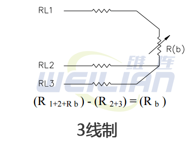
The working principle of the 3-wire circuit is to measure the resistance between # 1 and # 2 (R 1+2) and subtract the resistance between # 2 and # 3 (R 2+3), leaving only the resistance of the RTD bulb (R b). This method assumes that the resistance of wires 1,2 and 3 are the same
The 4-lead configuration will cause resistance elimination only if the transmitter can measure true 4-wire resistance. Even if the AWG, length and/or composition of all 4 wires are different, the real 4-wire resistance measurement can effectively eliminate the lead resistance error.
The 4-wire structure is mainly used in laboratories requiring high precision. In a 4-wire RTD temperature sensor, the actual resistance of the lead can be determined and removed from the sensor measurement.
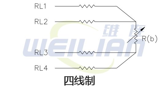
The 4-wire circuit is a real 4-wire bridge. Its working principle is to use wires 1 and 4 to supply power for the circuit and wires 2 and 3 to read. This true bridge method will compensate for any differences in lead resistance.
任何配置都可以互换吗?
A 4-lead RTD temperature sensor can usually be used as a 3-lead RTD by eliminating (or tying) one of the leads
4-lead RTD temperature sensors can be used as 2-lead RTDs by combining (shorting) common leads (usually with similar colors - white/white and red/red)
Warning: Combining common leads eliminates the benefits of lead resistance elimination
A 3-lead RTD temperature sensor can be used as a 2-lead RTD through a combination (short circuit) of common leads (usually similar in color)
Warning: Combining common leads eliminates the benefits of lead resistance elimination
