
PT100 temperature sensor wiring
PT100 wiring method - 2, 3 or 4 lines?
The wiring of the PT100 temperature sensor is different from other temperature sensors, especially thermocouple. It is important to connect the sensor correctly, otherwise the measuring instrument may give incorrect readings or there is no reading at all.
Conductor material
Cables used to connect the PT100 temperature sensor usually have copper -based conductors. In our own sensors, we use copper plating; tin plating, silver plating or nickel plating depending on the temperature range. However, pure copper is allowed.
For very high temperatures, we use nickel -based cables. Please note that the resistance of nickel is about 5 times that of copper, so you should always use the 3 or 4 -line connection system (see below).
The conductor size does not need to be very large. For example, without using a power cord, the instrument line is enough. We usually use 7/0.2mm and 24AWG multi -stock conductors in our own sensors. There is no problem even if the length of the cable is several meters. Of course, large cables can be used for long cable lengths, but this usually only increases unnecessary costs to shorter operations. For long cable operation, we recommend using the temperature transmitter.
Cable insulation
The types of cables that you choose to connect and measuring instruments will depend on the operating conditions of the process. Many of the sensors we provide have a flying wire that is directly connected to the instrument. The cable is carefully selected to meet the temperature requirements of the application and other environmental requirements. This may include chemical resistance or waterproofing.
We usually use cables with one of the following four types of insulation:
PVC
PVC is the preferred insulation material for almost all cables we see in daily life. Everything is PVC from the power cord to the leader of the headset and the phone. Generally speaking, due to its limited working scope, PVC is not a very commonly used cable in many temperature applications. Standard PVC is only applicable to the range of -10 to +70 ° C. The more commonly used version of the industry will expand the upper limit to 105 ° C. There are still many applications in this range. If the application allows PVC, then it is the lowest cost choice.
Silicone Rubber
If flexible, then silicon rubber is the best choice. Any cable using silicon rubber is more flexible than almost any other types of cables, and its operating temperature is very useful, with -60 to +180 ° C. Special versions can be run at 240 ° C, making it a more expensive alternative to polytrafluorolytic products.
Silicon rubber is an excellent adhesive material, which is the first choice for the probe of moisture -proof.
Polytefluoroethylene
It may be the most common cable used in temperature sensor manufacturing, PTFE and more common PFAs to handle extensive application requirements. Polytetrafluoroethylene is an insulating band entangled on the cable and sintering, and PFA is a form of squeezing. These materials compose part of a set of materials called fluoric polymers, indicating that fluoride is used in the composition of the material. Others include FEP, ETFE (TEFZEL) and FPM/FKM (Viton).
The working temperature range of these materials is -268 ° C (5K, -450 ° F) to +250 ° C. It is worth noting that the material still maintains good flexibility when it is as low as -75 ° C, but when it is lower than the temperature, we recommend that the cables are used staticly.
In addition to the extensive temperature range, these materials are also known for their actual chemical inertia, and they can be used with confidence without the existence of almost any material without the risk of degradation.
This material has extremely low friction coefficients (ranked third in all known materials) and has strong hydrophobicity. This means that it exclude water and other substances, making it extremely difficult to combine. Although we have the ability to chemically etch a fluoride polymer material before sealing, we recommend choosing other materials for moisture -proof components as much as possible.
Glass fiber
In some applications, additional mechanical protection needs to be provided for cables. The best way to achieve this goal is to use stainless steel flexible armor or catheter. It has various levels of stainless steel to choose from to meet cost and durability requirements. Although armored provides mechanical protection, it does not provide any additional waterproof.
PT100 wiring diagram
Cable shielding or shielding
In many applications, there is no need to provide ground shielding. However, there is indeed a shielding inside many cables. This shielding usually uses copper -plated fabrics instead of tape shielding, because it will withstand a wider temperature range.
Unless there are requirements, we will not stop the shielding as the tail that can be grounded, but this is available when necessary. According to experience, our customers will not encounter electrical noise problems when using such sensors. However, if you need to be continuously grounded through the entire sensor, this function can be provided.
The additional advantage of using weaving and shielding in the cable is that it provides additional mechanical strength. This is particularly favorable in the application of the cable protective cover.
PT100 temperature sensor wiring
Basic structure
The basic structure of the PT100 temperature is based on the precision resistance of the measurement point in the component, and is connected to the measurement instrument through a section of the cable. The cable may also include other components, such as interconnection and temperature transmitter. However, in all cases, there must be some electrical connection between the sensing element and the next component in the system.
Obviously, when using the PT100 RTD temperature sensor to measure the temperature, we are only interested in the resistance of the sensor element. However, any component added to the measurement circuit, including the wires or cables used, also has its own resistance. If you don't consider it carefully, this may cause measuring errors.
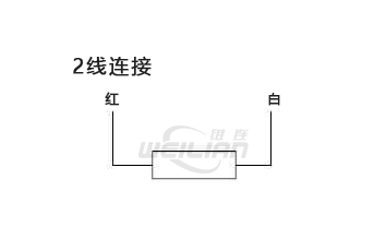
2 line PT100 RTD temperature sensor wiring system
Although two -line connection can be used to connect the PT100 temperature sensor, you should understand that the measurement error will be introduced due to the resistance of the lead. This is because the measurement instrument will measure the total resistance of the measurement circuit, not just the total resistance of the sensing element itself.
If the resistance of the resistance of the temperature of each degree Celsius is only 0.3851Ω, the connection cable with a resistance of only 1Ω will also cause an error of about +2.6 ° C.
Having said that, the two -line connection is often used, and the process parameters create many sensors with this type of connection type. For machine manufacturers with very short cable lengths, it is usually used as a low cost solution. The two -line connection is suitable for the following special circumstances: -
● Application for occasions with low accuracy requirements.
● The sensor cable is very short.
● The error is determined by testing and application of the offset of the instrument.
If your application needs do not belong to this, there is a standard method for compensation for the binding resistance.
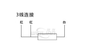
3 Line PT100 RTD temperature sensor wiring system
Add the third wire and connect to the side of the measurement element to help compensate the lead resistance. Each wire in the three wires used in the measurement circuit is the same in the conductor size and length, which is very important. This is because the measurement results are average. Only when all three wires have the same resistance can they provide good accuracy.
The working principle of the 3 line connection specification is to measure the resistance value through the detector, and obtain the second resistance value by a pair of wires connected to the side of the detector. The resistance value of the isolated measurement component is obtained from the total amount of the resistance.
So far, the three -line connection is the most common type of wiring type used in the PT100 temperature measurement. Many instruments use this connection method, including temperature transmitters, temperature controllers, panel monitors and data recorders, and in many cases, if the 2 -line system is used, it will not run normally.
If you use the 4 -wire sensor and 3 wire, you can simply ignore the 4 lines and hang it.
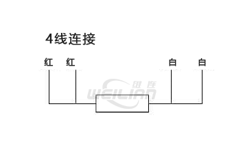
4 line PT100 RTD temperature sensor wiring system
In order to obtain the maximum accuracy, you should choose the four -line PT100 RTD temperature sensor specification. This measurement system is the only way to fully compensate all the binding resistors in the measurement system, even if each wire has different resistors.
The measurement system uses a pair of wires to carry the incentive current for measurement, and the second pair of wires are used to measure the resistance of the sensor by measuring the voltage.
Because the 4 -line connection method can fully compensate all the lead resistance, we strongly recommend using this method when using high -specification PT100 temperature sensors (e.g., 1/5 or 1/10 din tolerance). We believe that designated high -capacity differential temperature sensors with relevant costs, and then using inferior measurement systems is a wrong economic approach. The four -line connection is mainly used for laboratories and calibration applications and anywhere that requires the highest accuracy.
PT100 thermocouple wiring
The term "PT100 thermocouple" is misleading because there is no type of sensor. The term is the merger of two different technical names. When specifying a thermocouple or PT100, it is important to determine which sensor you use, because they cannot be swapped.
It is worth pointing out that in general, the tail color of the PT100 temperature sensor is red and white. Obviously, if you have three or four tails, the sensor is obviously a PT100 temperature sensor connected to 3 or 4 lines. However, if the sensor has two tails, one red and one white, can you be sure that it is the PT100 temperature sensor?
Unfortunately, the answer is not necessarily "yes." Many sensor manufacturers will use the same 2 -core cable as the PT100 for thermal resistance. There are also some thermocouple types identified with red and white tails, even when using the American ANSI color code. When color codes are performed in accordance with the German DIN standard, the R and S -type compensation cables also have red and white tails, but because of its applicable application types, it is unlikely to cause confusion.
To actively identify the sensor, you should check other test methods where you have any questions.
PT100 transmitter wiring
Another confusion source about the PT100 temperature sensor wiring is the temperature transmitter in the measurement system. You need to check the wiring description of the type of transmitter you use, but in general, they can summarize the following:
The temperature transmitter with 4-20mA output
Whether these are head transmitters or DIN rail transmitters, you should find two sets of connections. One set is "input" and the other is marked as "output".
For the 3 -line sensor input, the input side usually has three terminals, or the 4 -line connection usually has four terminals. You should follow the wiring diagram to ensure that the single white line (for 3 lines) is placed on one side of the circuit, and the two red lines are placed on the other side.
The output usually has only two terminals, because the 4-20mA device will definitely be powered by the circuit. In other words, the two lines connected to the output provide power input, but also output the MA signal.
Temperature transmitter with 0-10VDC output
These are not common in the temperature industry, but they do exist. The only difference is that there will be three terminals of the output of the transmitter instead of two. This is because single -pair conductors cannot provide power input and signal output at the same time. The three terminals are marked with the words "power+VE", "signal -VE" and "grounding" (or similar words, pay attention to the common grounding of power and signals).

